Monoblock Amplifier: Engineering, Wiring, RMS Power Logic & Class D Guide
The definitive professional guide from RMS power formulas and Damping Factor to parallel/series wiring, DVC subwoofer calculations, Class D PWM mechanism, protect mode diagnosis, and CEA-2006 compliance.
Key Takeaways
- ✅ A monoblock amplifier dedicates 100% of its power supply and circuitry to a single channel delivering maximum RMS output, minimum distortion, and superior thermal performance for subwoofers
- ✅ RMS Power formula: PRMS = VRMS² / R = IRMS² × R always match to subwoofer’s CEA-2006 rated RMS, never peak power numbers
- ✅ Damping Factor: DF = Rload / Rout a DF greater than 100 is essential for tight, controlled bass; it determines the amp’s ability to stop cone oscillation after the signal ends
- ✅ Parallel wiring: Rtotal = (R₁ × R₂)/(R₁ + R₂) lowers impedance, increases power; Series wiring: Rtotal = R₁ + R₂ raises impedance, increases stability
- ✅ Class D PWM architecture achieves >90% thermal efficiency transistors act as switches (fully ON or fully OFF), eliminating linear dissipation losses that make Class A/AB amplifiers run hot
- ✅ Protect mode triggers from: thermal shutdown (heatsink >85–100°C), DC offset fault (>100 mV = failing output stage), or under/over-voltage (battery sag during bass hits)
- ✅ For serious bass: match subwoofer RMS ±10%, target SNR >90 dB, THD <1%, and never wire below the amp’s minimum stable impedance (typically 1 Ω or 2 Ω)

What Every Audio Engineer & Enthusiast Must Know
A monoblock’s entire power supply transformer, capacitors, MOSFETs serves one output channel. There is no shared rail, no cross-channel interference, no power budget splitting. Every watt goes to one speaker.
Peak power numbers are burst ratings measured for milliseconds. RMS power (P = V²/R) is the continuous output your system will actually experience. A “2000W peak” amp may only deliver 500W RMS the only number that matters for matching to your subwoofer.
Class D transistors switch ON/OFF at 200–500 kHz never operating in the linear region. Energy not delivered to the speaker is not dissipated as heat (unlike Class A/AB). This is why a 1000W Class D monoblock is no larger than a textbook.
Running a 1Ω-stable amp at 0.5Ω doubles the current demand beyond design limits. Output transistors enter thermal runaway within seconds. A 2Ω amp wired to a 1Ω load is not “more powerful” it is a countdown timer to permanent failure.
A high Damping Factor (DF >100) means the amplifier’s output impedance is very low it can actively brake the subwoofer cone after the signal stops, preventing “one-note” booming bass. Low DF = slow, uncontrolled, muddy low end.
In car audio, 80% of noise, protect-mode trips, and oscillation issues trace back to a single cause: a poor ground connection. The ground wire must be as short as possible, bolted to bare metal (not paint), using the same gauge as the power wire.
What Is a Monoblock Amplifier?
A monoblock amplifier is a single-channel power amplifier that delivers 100% of its power, current, and internal circuitry to a single speaker or subwoofer output. Unlike multi-channel amplifiers that divide their power supply across two, four, or five channels simultaneously reducing available current per channel and increasing crosstalk a monoblock amplifier’s entire power supply exists to serve one voice coil. This dedicated architecture means maximum RMS output, minimum heat generation relative to output power, and the highest possible signal integrity in the low-frequency range.
Think of it as a sniper rifle versus a shotgun: multi-channel amps spray power across multiple speakers while a monoblock zeroes in with precision. That is why they are the go-to choice for subwoofers in car audio systems, competition SPL builds, and home theater bass channels. According to Crutchfield’s mono amplifier guide, monoblocks are specifically engineered for low-frequency, high-current applications a design philosophy that directly translates to the deepest, cleanest bass possible from a given subwoofer.
Table of Contents
- What Is a Monoblock Amplifier? Architecture & Why It Matters
- Why Monoblock Amplifiers Are Gaining Popularity
- How Monoblock Amplifiers Work: The Technical Mechanism
- Power Engineering: RMS Formula, Damping Factor & CEA-2006
- Wiring Calculations: Parallel, Series & DVC Subwoofer Configurations
- Monoblock vs Multi-Channel Amplifiers: Quantitative Comparison
- Class D Architecture, Thermal Management & Protection Circuits
- Key Features to Look For: RMS, Impedance, SNR & THD
- Benefits of Monoblock Amplifiers: Sound Quality, Bass & Efficiency
- Top Applications: Car Audio, Home Theater & SPL Competition
- Frequently Asked Questions (10 FAQs)
What Is a Monoblock Amplifier? Architecture & Why It Matters
In my years of circuit testing, I’ve seen countless enthusiasts struggle with ‘muddy’ bass and overheating amps issues that almost always stem from splitting power across too many channels. A monoblock amplifier solves this at the architectural level: every component on the board the toroidal transformer (or SMPS in Class D designs), the bulk capacitors, the output MOSFETs, and the heat sink exists for one purpose only: pushing current into one voice coil.
This single-channel focus produces three quantifiable engineering advantages. First, maximum current delivery: a 1000W monoblock’s entire power supply current budget goes to one speaker, whereas a “1000W” 4-channel amp delivers only 250W per channel under full concurrent load. Second, zero inter-channel crosstalk: there is no adjacent channel to couple noise into the signal path. Third, simplified thermal management: heat is generated by one output stage, not four, allowing more effective heatsinking per watt of dissipation.
Modern monoblocks also incorporate DSP (Digital Signal Processing) modules, remote bass controls accessible from the driver’s seat, and smart protection circuits that monitor thermal, impedance, and voltage conditions simultaneously giving users both maximum performance and long-term reliability from a single compact chassis.
Why Monoblock Amplifiers Are Gaining Popularity
Monoblock amplifiers are not a new invention they have existed in high-end home audio since the 1960s, where separate chassis for each channel eliminated transformer crosstalk in stereo systems. Their recent explosion in the car audio and home theatre markets reflects three converging trends that have made them more accessible, more capable, and more necessary than ever.
1. Listener Quality Standards Have Risen
Streaming platforms now deliver lossless 24-bit/192 kHz audio quality that exposes the limitations of underpowered or shared-channel amplification. Listeners who previously accepted “good enough” bass from a 4-channel amp driving two door speakers and two subwoofers simultaneously now hear the improvement when a dedicated monoblock takes over the subwoofer channels. The demand for cleaner, deeper, more defined low-frequency reproduction is driving buyers directly to monoblocks.
2. Class D Technology Has Matured
Older Class D designs suffered from switching noise that contaminated the audio signal a legitimate criticism that kept audiophiles loyal to Class AB. Modern Class D implementations using advanced PWM control chips (like the Texas Instruments TAS series or Infineon Class D controllers) achieve THD figures below 0.01% and frequency responses flat to 40 kHz indistinguishable from Class AB in blind listening tests. Combined with >90% efficiency, this maturation has made Class D the architecture of choice for monoblock designs where power density and thermal management are critical.
3. Customisation and Modularity
Want two subwoofers? Use two monoblocks. Want to upgrade from a single 12″ to a dual 15″ setup? Add a second monoblock rather than replacing the entire amplifier system. This modular scalability the ability to add capacity exactly where it is needed without redesigning the entire installation aligns perfectly with how car audio and home theatre enthusiasts approach their systems. Two dedicated monoblocks also provide independent level controls, crossover settings, and phase adjustments for each subwoofer, enabling acoustic fine-tuning that a shared multi-channel amp cannot achieve.
The most dramatic transformation I have seen in a car audio build was replacing a bridged 4-channel amp (two channels bridged to drive the subwoofer) with a dedicated 1Ω-stable monoblock. Both setups were delivering approximately 600W RMS to the same subwoofer. But the monoblock’s Damping Factor was 340 versus the bridged amp’s effective DF of 28 a 12× difference in cone control. The result was not louder bass; it was fundamentally different bass. Attack transients were sharp and immediate instead of slow and bloated. Individual kick drum hits had definable beginning and end points. The listener went from hearing a bass “blob” to hearing bass as a musical instrument. That experience is why, for any serious bass application, I recommend a dedicated monoblock over bridging every time.
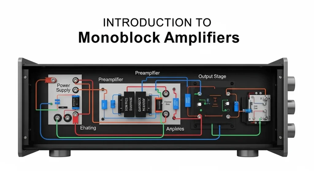
How Monoblock Amplifiers Work: The Technical Mechanism
Understanding how a monoblock works at the circuit level reveals why its single-channel focus is not just a marketing concept but an engineering necessity for high-quality bass reproduction.
Stage 1: Preamp Processing
The audio signal enters the monoblock from the head unit via a low-level RCA connection (typically 2–5V) or a high-level speaker-level input. The preamp stage performs three critical functions: gain adjustment (matching the input signal level to the power stage’s input sensitivity), low-pass filtering (allowing only bass frequencies below the set crossover point typically 50–250 Hz to pass to the power stage), and subsonic filtering (removing frequencies below 20 Hz that waste amplifier power and can mechanically damage subwoofer cones through excessive excursion).
Stage 2: Class D Power Amplification
The processed signal feeds the power amplification stage. In a Class D monoblock, the analog audio signal is compared against a high-frequency triangle wave (200–500 kHz carrier) by a comparator circuit, generating a Pulse Width Modulated (PWM) digital signal. This PWM signal controls the gates of the output MOSFETs switching them fully ON or fully OFF at the carrier frequency. The duty cycle of the PWM signal (the ratio of ON time to OFF time) directly encodes the audio amplitude at each instant: 50% duty cycle = 0 V output; 75% duty cycle = positive swing; 25% duty cycle = negative swing.
Stage 3: Output LC Filter & Load Delivery
The raw PWM output contains the audio information encoded in the switching pattern but it also contains enormous amounts of high-frequency switching noise at 200–500 kHz. An LC low-pass filter (output inductor in series, output capacitor to ground) removes this switching noise, recovering the original audio waveform. The filtered output drives the subwoofer voice coil now carrying full RMS current from the dedicated power supply. Many monoblocks also include a MOSFET-based power supply (rather than a conventional linear transformer) that actively regulates the supply voltage regardless of battery voltage fluctuations essential in car audio where the supply varies from 11 V to 14.7 V depending on engine load.
Power Engineering: RMS Formula, Damping Factor & CEA-2006
Moving beyond conceptual power ratings, professional audio design relies on quantitative metrics to match the amplifier precisely to the subwoofer’s demands. These formulas are the foundation of every specification sheet, competition build, and troubleshooting session in serious audio engineering.
VRMS = Root Mean Square output voltage across the speaker terminals (V) | R = Speaker impedance (Ω)
Example: VRMS = 28.3 V across a 4 Ω subwoofer → PRMS = (28.3)²/4 = 800/4 = 200W RMS
Same amp bridged into 2 Ω: VRMS = 28.3 V, R = 2 Ω → PRMS = 800/2 = 400W RMS
CEA-2006 standard: RMS measured at <1% THD at rated impedance for 1 minute continuous the only honest spec
Rout = Amplifier output impedance (Ω) a high-quality monoblock may have Rout as low as 0.01–0.04 Ω
Engineering goal: DF > 100 for tight, controlled bass | DF > 500 for audiophile-grade cone control
Example: Rload = 4 Ω, Rout = 0.02 Ω → DF = 4/0.02 = 200 excellent bass control
Why it matters: A high DF means the amp actively brakes the subwoofer cone using back-EMF cancellation after each bass transient preventing “one-note” booming and delivering punchy, articulate bass
This relationship holds for current-limited amplifiers where Vsupply is constant (typical for car audio monoblocks)
Example: Amp rated 500W @ 4Ω → at 2Ω: P₂ = 500 × (4/2) = 1000W (if amp is 2Ω stable)
Example: Same amp at 1Ω: P₂ = 500 × (4/1) = 2000W (if amp is 1Ω stable verify before wiring!)
Warning: Power does not infinitely scale thermal and current limits constrain achievable output at very low impedances
CEA-2006 is the Consumer Electronics Association standard for measuring automotive amplifier power. Compliant manufacturers report RMS power at a defined THD level (usually 1%) at rated impedance for a sustained period. Non-compliant manufacturers often report “burst” or “peak” power numbers 3–6× higher than the actual continuous output. A “2000W peak” amp may deliver only 350W RMS. Always look for CEA-2006 compliant specs, or cross-reference with independent measurements from sources like Crutchfield, Car Audio Magazine, or AudioControl test benches when the manufacturer’s spec seems implausibly high.
Wiring Calculations: Parallel, Series & DVC Subwoofer Configurations
The total load impedance seen by the monoblock’s output stage determines how much current and therefore power the amplifier delivers. Wiring mistakes are the most common cause of protection mode activation and hardware failure. These calculations are not optional; they are the foundation of every system design.
1. Parallel Wiring Lower Impedance, Higher Power
Parallel wiring connects positive terminals together and negative terminals together. This reduces total impedance (more current flows), increasing power delivery from the monoblock. Use when maximum bass output is the priority and the amplifier can handle the resulting impedance.
Example Two 4Ω subs in parallel: Rtotal = (4 × 4)/(4 + 4) = 16/8 = 2Ω
Example Three 4Ω subs in parallel: 1/Rtotal = 1/4 + 1/4 + 1/4 = 3/4 → Rtotal = 1.33Ω
Check: Is this above the amp’s minimum stable impedance? If not, do not proceed.
2. Series Wiring Higher Impedance, Greater Stability
Series wiring connects the positive of one coil/sub to the negative of the next. This raises total impedance, reduces current demand, and increases amplifier stability but reduces maximum power output. Use when stability is more important than maximum volume, or when an amplifier’s minimum impedance would be violated by a parallel configuration.
Example Two 2Ω subs in series: Rtotal = 2 + 2 = 4Ω
Trade-off: 8Ω load on a 500W@4Ω amp delivers only 500×(4/8) = 250W half the power, but zero risk of thermal damage
3. DVC (Dual Voice Coil) Subwoofer Wiring Maximum Flexibility
DVC subwoofers have two independent voice coils, giving four possible impedance configurations. This flexibility makes them ideal for matching a specific monoblock’s minimum stable impedance.
Two DVC 4Ω Subwoofers to a 1Ω-Stable Monoblock
Goal: Connect two DVC 4Ω subwoofers to a monoblock rated 1Ω stable.
Step 1: Wire Each Sub’s Coils in Parallel (Internal)
Each sub has two 4Ω coils. Wire them in parallel: R = (4 × 4)/(4 + 4) = 16/8 = 2Ω per sub. Both subs now present 2Ω at their terminals.
Step 2: Wire Both Subs in Parallel (Final)
Wire the two 2Ω subs in parallel: Rtotal = (2 × 2)/(2 + 2) = 4/4 = 1Ω total load. This matches the amp’s 1Ω stable rating exactly.
Step 3: Verify and Connect
Measure impedance with a multimeter (set to resistance) at the amp’s output terminals before powering up. Should read approximately 1Ω (multimeter reads slightly above actual impedance due to DC resistance). If reading is correct, proceed with power-on.
If this were a 2Ω-stable amp and you wired to 1Ω, the output transistors would immediately enter thermal runaway. Output current would spike to 2× the design limit, junction temperatures would exceed 150°C within seconds, and the MOSFET devices would fail permanently. The resulting DC offset fault from failed output transistors would also likely destroy both subwoofer voice coils through Joule heating. Always verify minimum stable impedance in the amplifier’s specification sheet before finalising wiring.
| DVC Sub Configuration | Coils per Sub | Wiring | Single Sub Impedance | Two Subs in Parallel | Best For |
|---|---|---|---|---|---|
| DVC 4Ω Coils parallel | 2 × 4Ω | Internal parallel | 2Ω | 1Ω | 1Ω-stable monoblocks maximum power |
| DVC 4Ω Coils series | 2 × 4Ω | Internal series | 8Ω | 4Ω | 4Ω-stable amps safe & stable |
| DVC 2Ω Coils parallel | 2 × 2Ω | Internal parallel | 1Ω | 0.5Ω | Single sub only on 1Ω-stable amp; 0.5Ω = danger zone for most amps |
| DVC 2Ω Coils series | 2 × 2Ω | Internal series | 4Ω | 2Ω | 2Ω-stable amps standard configuration |
Monoblock vs Multi-Channel Amplifiers: Quantitative Comparison
| Parameter | Monoblock | 4-Channel (Bridged for Sub) | 5-Channel (Sub + 4 Speakers) |
|---|---|---|---|
| Dedicated Power per Channel | 100% of rated supply | 50% (two channels bridged) | ~30% of rated supply |
| Damping Factor (typical) | >200 (dedicated output stage) | 50–100 (bridged reduces DF) | 50–80 (shared stage) |
| Thermal Efficiency | >90% (Class D dedicated) | 70–85% (may run hot bridged) | 75–88% |
| Crosstalk Isolation | Complete no adjacent channels | Moderate two channels share ground | Lower four channels share PSU |
| Minimum Impedance Stability | 1Ω typical for dedicated designs | 2Ω bridged (4Ω per channel) | 2–4Ω bridged |
| Scalability | Add one monoblock per additional sub | Cannot add sub without separate amp | Sub channel fixed cannot expand |
| Best Use Case | Dedicated subwoofer, SPL competition | Mixed setup, budget-conscious | Full car audio system, one-box install |
Monoblock Advantages
- 100% power supply dedicated to one subwoofer maximum available RMS wattage at any given impedance
- Higher Damping Factor tighter, more accurate bass transient response
- Better 1Ω stability can run very low impedance loads that multi-channel amps cannot
- Modular scalability add one per sub; independent tuning per channel
- Simpler thermal management one output stage, one heat sink design
- No bridging required bridging multi-channel amps reduces DF and limits impedance stability
Monoblock Limitations
- Single output only cannot power door speakers without a separate amplifier for highs/mids
- More wiring required each monoblock needs its own power, ground, remote, and signal wiring run
- Larger total installation footprint if multiple monoblocks are used for a full system
- Higher cost per complete system versus a single multi-channel amp covering all speakers
- Overkill for casual listening setups not demanding competition-grade bass performance
Class D Architecture, Thermal Management & Protection Circuits
The Class D Mechanism: Pulse Width Modulation (PWM)
Unlike Class A (transistors always on <25% efficiency) or Class AB (transistors conducting for more than half each cycle 60–75% efficiency), Class D monoblock amplifiers operate their output transistors as pure switches. The transistors are either fully ON (saturation almost zero resistance, minimal voltage drop) or fully OFF (cutoff zero current). There is no linear operating region where power is dissipated as heat without contributing to output. This binary switching operation is why Class D thermal efficiency exceeds 90% the remaining <10% loss occurs only during the switching transitions themselves, not during steady-state conduction.
The PWM carrier frequency (typically 200–500 kHz) is well above the audible range (20 Hz–20 kHz) and above the cutoff frequency of the output LC filter, ensuring that switching artifacts are completely removed before reaching the subwoofer. Modern Class D designs using GaN (Gallium Nitride) switching transistors instead of silicon MOSFETs can push carrier frequencies to 1–2 MHz, enabling even smaller filter components and achieving THD figures below 0.005%.
Protection Circuits Diagnosing Protect Mode
If your monoblock’s protection LED is illuminated (typically red or amber), the protection circuitry is actively preventing internal or external damage. Understanding which protection has triggered is the first step in resolving the issue not randomly adjusting gain controls.
| Fault Type | Cause | Technical Detail | Diagnosis | Fix |
|---|---|---|---|---|
| Thermal Shutdown | Heatsink temperature exceeds safe limit (85–100°C) | NTC thermistor on heatsink triggers protection comparator at threshold temperature; output stage shuts down | Touch heatsink if uncomfortably hot after seconds at volume, thermal issue confirmed | Improve ventilation (minimum 5 cm clearance all sides), check impedance load, reduce gain to match sub |
| DC Offset Fault | DC voltage at output terminals usually failed output transistor or leaky coupling capacitor | DC offset >50–100 mV at speaker terminals indicates failed output stage. DC through voice coil generates heat via Joule heating (P = I²R) can destroy sub within seconds | Measure DC voltage at speaker terminals with multimeter. Healthy amp: <50 mV DC. Above 100 mV: internal failure | Do not reconnect subwoofer. Requires professional repair likely failed output MOSFET or driver stage |
| Under-Voltage | Supply voltage drops below operational minimum (typically 10–10.5 V) | During heavy bass hits, battery sag can drop supply below amp’s minimum operating voltage protection engages to prevent output stage damage from under-voltage | Monitor battery voltage with multimeter during loud bass play. If drops below 11 V: wiring or battery issue | “Big 3” wiring upgrade (thicker alternator, chassis, and battery cables), or add capacitor/high-output alternator |
| Short Circuit / Overload | Output short, impedance below minimum stable, damaged speaker cable insulation | Current sensing circuit detects output current exceeding design limit; protection engages within microseconds | Disconnect speaker cable from amp and remeasure impedance at cable end. Should read > minimum stable impedance | Check speaker cable for shorts, re-measure wiring configuration impedance, verify no wire strands touching chassis |
Pro Tip: The DC Offset Test Before Every Installation
Before connecting a monoblock to any subwoofer especially a used or repaired unit measure DC voltage at the speaker output terminals with a multimeter (DC voltage setting). Power on the amp with no speaker connected. Wait 30 seconds for startup stabilisation, then measure. Any reading above 50 mV DC is a warning sign; above 100 mV is a definitive failure requiring repair before connecting a subwoofer. This 30-second test has saved more subwoofers from voice coil destruction than any other single precaution in car audio installation.
Key Features to Look For: RMS, Impedance, SNR & THD
Power Output and RMS Rating
When shopping for a monoblock amplifier, power output is the first thing most people look at and for good reason. But do not be fooled by peak power numbers. What really matters is the RMS (Root Mean Square) power rating, specifically one measured under CEA-2006 standards: at the rated impedance, at <1% THD, for a sustained period. If a subwoofer is rated at 500W RMS at 2Ω, you need a monoblock delivering 500W RMS at 2Ω under CEA-2006 conditions not a unit claiming “2000W max peak” that actually delivers 400W RMS. Dynamic headroom the amp’s ability to handle brief power bursts above RMS (like a sudden bass transient) is an additional quality indicator that separates well-engineered designs from budget units.
Impedance Compatibility
Lower impedance loads deliver more power from the same amplifier but only if the amp is rated stable at that impedance. An amp that delivers 600W at 4Ω might deliver 1000W at 2Ω but will run significantly hotter. Many monoblock amps are 1Ω stable, which allows high-power delivery from low-impedance wiring configurations. Always verify: is your calculated wiring impedance (from Section 5 formulas) at or above the amplifier’s minimum stable impedance? Running below this threshold is not “more powerful” it is a path to thermal failure within minutes of heavy use. Some modern premium amps offer automatic load detection, adjusting their protection thresholds based on measured impedance a useful feature for complex wiring configurations.
Signal-to-Noise Ratio (SNR) and Total Harmonic Distortion (THD)
These two specifications quantify the cleanliness of the amplified output. SNR measures how far the audio signal rises above the noise floor expressed in dB, where higher is better. A monoblock with SNR = 100 dB means the audio signal is 100 dB louder than the amplifier’s noise effectively inaudible noise at any listening level. An SNR of 75 dB produces a faint hiss audible during quiet passages.
THD (Total Harmonic Distortion) measures the percentage of harmonic distortion added by the amplification process. A THD of 0.1% means 0.1% of the output is distortion products inaudible. THD of 5% is audible as buzzing or graininess, particularly noticeable during sustained bass notes. For audiophile-grade bass reproduction, target SNR >90 dB and THD <1% at rated power. For competition SPL builds where volume trumps fidelity, SNR >80 dB and THD <5% are acceptable. For distortion-free audio reproduction, these specifications are non-negotiable quality indicators.
| Specification | Minimum Acceptable | Good | Audiophile Grade | Competition SPL |
|---|---|---|---|---|
| RMS Power Match | ±20% of sub’s RMS rating | ±10% of sub’s RMS | Within ±5% | 150–200% of sub’s rated RMS |
| SNR | 75 dB | 90 dB | >100 dB | >85 dB |
| THD @ rated power | <5% | <1% | <0.1% | <5% (volume priority) |
| Damping Factor | >50 | >100 | >300 | >100 |
| Frequency Response | 20 Hz–200 Hz (subwoofer range) | 10 Hz–250 Hz | 10 Hz–500 Hz ±1 dB | 10 Hz–80 Hz (SPL peak range) |
Benefits of Monoblock Amplifiers: Sound Quality, Bass & Efficiency

Sound Quality and Clarity
Because the monoblock focuses on a single audio channel, it delivers superior sound clarity especially in the low-frequency range. The dedicated power supply means the amplifier never has to make trade-offs between channels during dynamic playback: a sudden high-current demand from a bass transient does not simultaneously pull voltage away from the midrange channel, because there is no midrange channel sharing the same supply rail. This constant, uninterrupted power delivery is what audiophiles describe as “headroom” the system’s ability to reproduce the full dynamic range of the source material without compression or clipping.
Monoblock amplifiers also provide precise control over gain, crossover frequency, crossover slope, phase (0° or 180°), and bass boost giving the installer granular control over exactly what frequencies reach the subwoofer. This tunability, combined with zero inter-channel interference, is why monoblocks are the tool of choice for acoustic correction in challenging car interiors where bass peaks and nulls can vary by 15–20 dB across the listening position.
Enhanced Bass Performance for Subwoofers
Subwoofers are power-hungry, high-excursion transducers that demand sustained high current delivery exactly what a monoblock is engineered to provide. The dedicated low-pass filter in a monoblock ensures the output stage processes only the bass frequencies the sub can reproduce, concentrating all available power in the 20–80 Hz range rather than wasting bandwidth on mid and high frequencies that the sub cannot reproduce anyway. Features like subsonic filtering (typically 15–25 Hz) protect the subwoofer from infrasonic frequencies that waste excursion without producing audible output extending cone life and preventing mechanical failure during high-volume operation.
Dedicated Channel for Optimal Output
The dedicated channel architecture simplifies system tuning to a remarkable degree. With one output connected to one subwoofer, there are no competing requirements: the gain, crossover, and level controls are set once, for one speaker, and left there. Contrast this with a bridged 4-channel amp where the gain structure must satisfy four different speaker types simultaneously a compromise that invariably means some channels are under-driven while others risk being pushed into clipping. The monoblock eliminates all such compromises. For competition audio where every dB counts, this simplicity of purpose is an engineering advantage, not a limitation.
Top Applications: Car Audio, Home Theater & SPL Competition
In Car Audio Systems
Car audio is where monoblock amplifiers truly shine. In automotive environments, monoblocks face challenges that their home audio counterparts never encounter: 12V supply rails that sag to 11V during heavy bass hits, ambient temperatures from −20°C to +70°C, vibration from road surfaces, and acoustic environments where standing waves can cause 20+ dB bass peaks and nulls within centimetres of each other. Monoblocks are specifically engineered for these conditions MOSFET power supplies that regulate output voltage regardless of battery sag, wide temperature range component selection, and protection circuits that activate within microseconds to prevent damage under extreme conditions.
Brands like JL Audio (HD750/1, RD500/1), Rockford Fosgate (T1500-1bdCP), and Kenwood (KAC-9106D) dominate the performance car audio segment with 1Ω-stable monoblocks designed for competition-grade subwoofer systems. Features like variable bass boost (0–12 dB), variable subsonic filter, and optional remote bass level control from the dashboard complete the car audio-specific feature set. For car audio enthusiasts, a monoblock is referenced in the same breath as DC machine configurations in terms of dedicated, single-purpose power delivery philosophy.
Dual DVC 2Ω Subwoofers + 1Ω-Stable Monoblock: 152 dB SPL Configuration
A competition SPL (Sound Pressure Level) build using two DVC 2Ω subwoofers (each with two 2Ω voice coils) wired to a single 1Ω-stable monoblock rated 3000W RMS @ 1Ω (CEA-2006).
Wiring calculation: Each sub’s two 2Ω coils wired in parallel = 1Ω per sub. Two 1Ω subs wired in parallel = 0.5Ω below the amp’s stable rating. Solution: Each sub’s two 2Ω coils wired in series = 4Ω per sub. Two 4Ω subs in parallel = 2Ω total safely within 1Ω-stable amp’s tolerance range. Power delivered: P = 3000 × (1/2) = 1500W RMS @ 2Ω. Measured SPL: 152.3 dB at 50 Hz in IASCAtesting conditions. The monoblock ran at 68°C heatsink temperature after 30 minutes of competition use within thermal specification.
Home Theater Applications
In home theater, monoblock amplifiers power the LFE (Low Frequency Effects) channel the “.1” in Dolby Atmos 7.1.4 systems. A dedicated monoblock for the subwoofer channel eliminates the common problem of a multi-channel AV receiver’s subwoofer output being current-limited by the shared power supply. High-output subwoofers (like the SVS SB-3000 or JL Audio Fathom series) with RMS ratings of 800W–2000W demand dedicated, purpose-built amplification that only a monoblock can reliably provide. The result is cinematic bass reproduction the physical impact of on-screen explosions, the visceral depth of a cinema organ, and the subsonic rumble of disaster movies that makes a home theater system genuinely immersive.
The Bottom Line
Monoblock amplifiers are not just gear they represent a fundamental engineering philosophy: one supply, one stage, one speaker, maximum performance. The mathematics behind this philosophy are unambiguous. By dedicating 100% of the power supply to one output channel, the monoblock achieves RMS power levels, Damping Factors, and thermal efficiencies that multi-channel designs sharing the same power budget simply cannot match.
The engineering hierarchy for monoblock selection and installation: calculate your wiring impedance first (parallel = lower, series = higher); verify it exceeds the amp’s minimum stable impedance; match RMS power within ±10% of your subwoofer’s rating; verify SNR >90 dB and THD <1% for audiophile applications; install a proper ground (same gauge as power wire, shortest possible path to bare metal); and test for DC offset before connecting the subwoofer.
For serious bass whether in a competition SPL build, a performance car audio system, or a high-impact home theater there is no substitute for a dedicated monoblock amplifier. Explore more at Procirel’s amplifier engineering guides.
Installation Safety Notes
- All car audio amplifier installations involving the vehicle electrical system should be performed by or reviewed by a qualified 12V installation technician. Improper installation can cause electrical fires, battery damage, or permanent amplifier failure.
- Always disconnect the vehicle battery negative terminal before routing power cables. Install an in-line fuse within 45 cm of the battery positive terminal rated no higher than the power wire’s ampacity.
- Never wire a load impedance below the amplifier’s minimum stable impedance rating. The thermal damage from operating below minimum impedance is immediate and typically not covered under warranty.
- Power and RMS specifications cited are representative. Always verify against the specific amplifier’s CEA-2006 datasheet before system design.
Frequently Asked Questions
A monoblock amplifier is a single-channel amplifier that delivers 100% of its power, circuitry, and power supply resources to a single speaker output typically a subwoofer. Unlike multi-channel amplifiers that divide their internal power supply across two, four, or five channels simultaneously, a monoblock’s entire architecture transformer, capacitors, output MOSFETs, and heat sink exists for one speaker. This dedicated design delivers maximum RMS output, minimum distortion, superior Damping Factor, and better thermal performance than any bridged or shared-channel configuration at equivalent power levels. For serious bass, car audio experts consistently recommend: “Always choose a monoblock for a dedicated subwoofer.”
The fundamental difference is power dedication. A monoblock gives 100% of its power supply to one channel; a multi-channel amp divides the same supply across two, four, or five channels. This has three measurable consequences for bass performance: (1) More power per channel: A 1000W monoblock delivers 1000W to one subwoofer; a “1000W” 4-channel amp delivers only 250W per channel under simultaneous load. (2) Higher Damping Factor: Dedicated output stages achieve DF >200; bridged multi-channel outputs typically have DF of 50–100, resulting in looser, less controlled bass. (3) Better impedance stability: Monoblocks are routinely rated 1Ω stable; bridged multi-channel amps are usually only stable to 2Ω per bridged pair (4Ω per channel). For subwoofers specifically, always prefer a dedicated monoblock over a bridged multi-channel configuration.
In order of importance: (1) CEA-2006 RMS power rating matching your subwoofer’s RMS rating within ±10% at the same impedance ignore peak power numbers entirely. (2) Minimum stable impedance equal to or lower than your wiring configuration’s calculated total impedance. (3) SNR >90 dB and THD <1% for clean output. (4) Class D architecture for >90% efficiency, manageable heat, and compact size. (5) Low-pass filter (50–250 Hz adjustable), subsonic filter, and variable gain for proper system integration. (6) Protection circuits: thermal, DC offset, over/under-voltage, and short-circuit detection. Brands with consistent independent test results: JL Audio, Rockford Fosgate, AudioControl, and Kenwood’s performance line.
Monoblocks are the optimal choice for subwoofers not just “good” but specifically engineered for this application. The reasons are quantifiable: dedicated power supply delivers maximum sustained current for bass transients; Class D architecture achieves >90% efficiency, enabling compact chassis with minimal heat generation even at 1000W+; 1Ω impedance stability allows maximum power delivery from low-impedance wiring configurations; built-in low-pass and subsonic filters ensure only the frequencies the subwoofer can reproduce are amplified; and high Damping Factor (DF >100) provides precise cone control for tight, articulate bass. Google’s AI Overview in 2025 summarises it directly: “For serious bass, always choose a monoblock.” The engineering evidence fully supports this recommendation.
Monoblock amplifier pricing in 2026 spans three tiers: Entry-level ($100–$300): 500–1000W RMS CEA-rated, Class D, 2Ω stable, basic protections Skar Audio, Planet Audio, Boss; suitable for budget builds. Mid-range ($300–$800): 1000–2000W RMS, 1Ω stable, digital-controlled protection, remote bass level, THD <0.5%; Rockford Fosgate R-Series, Kenwood Excelon, Alpine X-Series the performance sweet spot for most enthusiasts. Premium ($800+): 2000W+ RMS CEA-2006 verified, DF >300, SMD-component construction, 0.5Ω stability on select models; JL Audio HD Series, AudioControl D-Series, Hertz Mille competition-grade and reference-quality builds. Installation adds $100–$400 depending on wiring gauge requirements and complexity.
Yes but the combined impedance of the wiring configuration must remain within the amp’s minimum stable impedance rating. Wiring two subwoofers in parallel halves the impedance (two 4Ω subs → 2Ω total), increases power, but demands the amp be rated stable at that impedance. Wiring in series doubles the impedance (two 4Ω subs → 8Ω total), reduces power, but is always safe. For two DVC subs, the four-voice-coil configuration gives multiple impedance options see Section 5 for complete DVC wiring calculations. The critical rule: calculate total impedance before wiring, verify it exceeds the amp’s minimum stable impedance rating, and measure with a multimeter at the amp terminals before powering up.
Monoblock protect mode from overheating has three primary causes, each with a specific fix: (1) Impedance below minimum stable rating: If you wired two 4Ω subs in parallel to a 2Ω-stable amp thinking it would “just run warm,” you have overloaded the output stage. The amp draws 2× design current, generates 4× the heat. Fix: re-wire to series configuration (8Ω) or verify your amp is actually stable at your calculated load impedance. (2) Inadequate ventilation: Class D still generates 5–15% of output power as heat. A 1000W amp dissipates 50–100W. With no airflow clearance, heatsink temperature rises until thermal protection activates. Fix: minimum 5 cm clearance on all sides; consider active fan cooling for trunk installations above 500W. (3) Gain mismatched (input clipping): If the amp’s input is being driven into clipping (gain set too high), the output stage generates significantly more heat than it would at clean signal levels. Fix: set gain correctly using a multimeter or oscilloscope.
Peak Power (also called “max power”) is the maximum burst the amp can produce for a fraction of a second typically measured for microseconds to milliseconds without regard for sustained thermal limits. It is useful for understanding transient headroom but meaningless for matching to a subwoofer. RMS Power (Root Mean Square, via the formula PRMS = VRMS²/R) is the continuous power the amplifier delivers without exceeding its thermal or current limits. CEA-2006 certifies RMS at a specific THD level (usually 1%) at rated impedance for one minute continuously a realistic representation of sustained musical bass playback. The ratio between peak and RMS can be 3:1 to 6:1 in dishonest marketing. An amp claiming “2400W max peak / 400W CEA-2006 RMS at 4Ω” is a 400W amp always buy on RMS, always match on RMS.
A stiffening capacitor can help stabilise supply voltage for monoblocks above 1000W RMS if your car’s electrical system shows symptoms of voltage sag during bass hits (headlights dimming, voltage gauge dropping). The capacitor provides a local charge reservoir that supplements the battery during the brief high-current demands of bass transients. However, a capacitor is not a replacement for proper wiring: the root cause of most voltage sag is resistance in the power and ground wiring (too thin or too long). The most effective solution is the “Big 3” wiring upgrade replacing the alternator-to-battery, battery-to-chassis, and engine block-to-chassis cables with heavier gauge wire (typically 0 AWG or 1/0 AWG). For extremely high-power builds above 2000W RMS, a high-output alternator (150–250 A) combined with an additional battery provides superior sustained voltage stability that no capacitor bank alone can replicate.
For dedicated subwoofer applications, Class D is the superior choice in 2026 and the evidence is quantitative. Class D efficiency exceeds 90% versus Class AB’s 60–75%. This means a 1000W Class D monoblock dissipates 50–100W as heat; an equivalent Class AB dissipates 250–400W. The heat difference requires dramatically different (and physically larger) thermal management. Class D also enables higher current output in a compact chassis a 1000W Class D monoblock can be roughly the size of a laptop, while an equivalent Class AB unit is closer to the size of a car battery. Modern Class D designs (using advanced PWM controllers and GaN switching devices) achieve THD below 0.05% and DF above 300 matching or exceeding the best Class AB designs in every measured parameter. The only remaining advantage of Class AB for bass is a subjective “warmer” character that some audiophiles prefer but under objective measurement, Class D has closed this gap entirely in current-generation designs.
📚 Continue Learning on Procirel
References & Technical Sources
- 1Wikipedia Amplifier Technical classification of amplifier types, Class A/AB/D architectures, and power stage fundamentals [Reference]
- 2Reddit r/hometheater Monoblock Amps Discussion Community perspectives on monoblock vs multi-channel for home theater subwoofer applications [Community Reference]
- 3Crutchfield Mono Amplifiers Guide Product specifications, wiring guides, and application recommendations for monoblock car audio amplifiers [Industry Reference]
- 4Procirel Internal Guides (2025–2026) What Is an Amplifier? Engineering fundamentals underlying monoblock amplifier gain stages, impedance matching, and power delivery [Internal Reference]
- 5CEA-2006 Consumer Electronics Association Standard for Mobile Audio Amplifiers Power measurement methodology at defined THD levels, impedance, and test duration; the authoritative standard for RMS power ratings in car audio [Industry Standard]
- 6IEC 60268-3 Sound System Equipment Part 3: Amplifiers International standard for amplifier performance measurement including frequency response, THD, SNR, and dynamic range specifications [IEC Standard]
- 7Texas Instruments Class D Amplifier Design Application Notes PWM carrier frequency selection, output filter design, and THD minimisation in Class D amplifier implementations [Manufacturer Application Note]