Power Supply Classification: 8 Types, Formulas & Complete Selection Guide (2026)
The definitive professional guide from the 8 core power supply types and efficiency/ripple formulas to Linear vs SMPS vs GaN comparison, 80 PLUS ratings, hold-up time, 12-step troubleshooting, and IEC 62368-1 compliance.
Key Takeaways
- ✅ There are 8 core power supply types classified by input/output: AC→DC, Regulated, Linear, SMPS, UPS, DC→DC, AC→AC, and High-Voltage each serving distinct applications and performance requirements
- ✅ Efficiency formula: η = Pout/Pin × 100% the basis for 80 PLUS certification; Titanium units deliver ≥94% efficiency even at 10% load
- ✅ Ripple voltage: ΔVripple ≈ Iload / (f × C) minimising ripple is critical for audio, sensors, and precision instruments; linear PSUs achieve <1 mV
- ✅ GaN SMPS now achieves 95–98.5% efficiency at ultra-compact size the 2026 standard for phone/laptop chargers, replacing traditional silicon SMPS
- ✅ Hold-up time ≥17 ms at 100% load is the minimum standard for servers and medical devices; short hold-up time indicates failing bulk capacitors
- ✅ Linear PSU: ultra-low ripple (<1 mV), 40–60% efficiency, ideal for audio/lab; SMPS: 85–98% efficiency, compact, universal choose based on noise tolerance and efficiency requirements
- ✅ In 2026, IEC 62368-1 replaces IEC 60065/60950 as the safety standard for audio/video and IT equipment power supplies; medical PSUs follow IEC 60601-1

What Every Engineer & Designer Must Know About Power Supplies
Choosing a PSU in 2026 involves efficiency class (80 PLUS Bronze→Titanium), ripple tolerance under dynamic loads, hold-up time, transient response, and IEC 62368-1/60601-1 compliance not just wattage rating.
Gallium Nitride (GaN) SMPS units achieve 95–98.5% efficiency at power densities above 100 W/in³ making them the 2026 standard for USB-C chargers, laptop adapters, and EV onboard chargers. Silicon MOSFETs are becoming legacy technology.
Ripple voltage on a DC rail causes noise in audio (audible hum), sensor drift, and ADC errors in microcontrollers. Linear PSUs achieve <1 mV ripple SMPS typically 50–150 mV without proper filtering.
Medical PSUs (IEC 60601-1) require ≤2× leakage current limits vs consumer grade, reinforced isolation, and 4,000 V dielectric withstand. Using a consumer PSU in medical equipment is a certification failure and patient safety risk.
Hold-up time (≥17 ms standard) is the PSU’s ability to sustain output after AC loss. Short hold-up indicates bulk capacitor degradation a common failure mode in aged SMPS units. Verify with oscilloscope, not just visual inspection.
Modern server and telecom PSUs use PMBus/I²C digital interfaces for real-time monitoring, dynamic voltage scaling, and predictive failure alerts mandatory for hyperscale data centres and Industry 4.0 automated production environments.
What Is a Power Supply and How Are They Classified?
A power supply is a device that converts electrical energy from a source (mains outlet, battery, or another power bus) into the specific voltage, current, and frequency that electronic equipment requires. Think of it as a precision flow controller for electricity without it, every device would receive unregulated mains power that would instantly destroy sensitive electronics. Internal power supplies are integrated into the device; external ones (like phone chargers) are separate units.
Power supplies are classified along multiple axes: by their input/output conversion type (AC→DC, DC→DC, AC→AC, DC→AC), by their regulation method (linear vs switching), by their efficiency class (80 PLUS Bronze through Titanium), by their intended application (consumer, industrial, medical, military), and by their protection features. In 2026, choosing the right power supply requires evaluating efficiency class, ripple tolerance under dynamic loads, hold-up time for mission-critical systems, and compliance with the latest IEC 62368-1 safety standard not just the wattage number. As a comprehensive overview of power supply classification shows, understanding these categories directly impacts reliability, EMI performance, and total cost of ownership.
📋 Table of Contents
- What Is a Power Supply? Core Function & Classification Framework
- 8 Types of Power Supplies: Complete Classification with Specs
- Linear vs SMPS vs GaN vs Digital: The Definitive Comparison
- Core Engineering Formulas: Efficiency, Ripple & Power Loss
- 80 PLUS Certification Explained: Bronze to Titanium
- Emerging Technologies: GaN, ACF, ZVS & PMBus Digital Control
- Real-World Case Studies: PC, Lab Bench & Industrial Motor Drive
- Quick Selection Guide: Which Power Supply Do You Need?
- 12-Step Professional Troubleshooting Guide
- Advanced Diagnostics: Hold-Up Time & MOSFET Failure Analysis
- Frequently Asked Questions (14 FAQs)
What Is a Power Supply? Core Function & Classification Framework
A power supply performs one fundamental function: converting available electrical energy into the precise form that a load requires. The mains outlet delivers 110–240 V AC at 50 or 60 Hz nearly every electronic device requires something different: stable 5 V DC for USB, 12 V DC for motors, 48 V DC for PoE switches, 400 V DC for server bus rails, or even thousands of volts for medical imaging. The power supply manages this conversion with four key qualities: correct voltage level, controlled current capacity, low output noise (ripple), and protection against faults.
The classification framework has evolved significantly by 2026. The simple linear-vs-switching distinction is now a subset of a broader taxonomy that includes: conversion direction (AC→DC, DC→DC, AC→AC, DC→AC), regulation method (linear, switching, resonant), semiconductor technology (silicon, GaN, SiC), control architecture (analog, digital PMBus), and application tier (consumer, industrial, medical, military, automotive). Understanding where a power supply falls in this framework determines its suitability for a given design and its compliance obligations. Intel’s power supply engineering guide provides excellent context for PC-specific requirements, while the IEC 62368-1 standard governs the broader consumer and IT equipment landscape.
Internal power supplies (built into the device desktop PC PSU, embedded industrial supply) share thermal management with the host system but reduce cable management complexity. External power supplies (phone chargers, laptop adapters, lab bench units) simplify the device design, are easier to replace, and can be certified independently. The 2026 trend in consumer electronics strongly favours external GaN chargers a single 140 W GaN unit can power a laptop, tablet, and two phones simultaneously, replacing four dedicated chargers.
8 Types of Power Supplies: Complete Classification with 2026 Specs
AC to DC Power Supplies

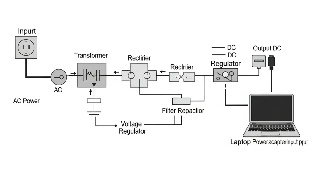
The dominant power supply type converts household AC (110–240 V, 50/60 Hz) into stable DC at the voltages electronics require. The conversion chain: transformer (optional in SMPS) → bridge rectifier (four diodes) → filter capacitors → voltage regulator. Every phone charger, laptop adapter, LED driver, gaming console PSU, and desktop computer uses an AC→DC power supply as its foundation. The output voltages span from 1.8 V (DDR5 memory) to 48 V (industrial and PoE) depending on the application.
2026 status: GaN-based AC→DC SMPS now dominates the charger market. Traditional silicon-based units are being phased out for loads under 300 W. ATX 3.0 spec adds the 16-pin PCIe 5.0 connector for graphics cards with 150 W transient spikes.
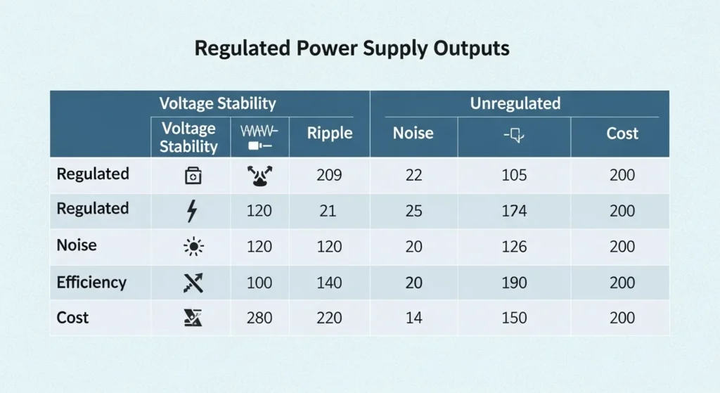
✅ Regulated vs Unregulated Power Supplies
| Type | Output Stability | Regulation Circuit | Best For | Price | 2026 Recommendation |
|---|---|---|---|---|---|
| Unregulated | Fluctuates ±10–30% with load/input | None transformer + rectifier only | Simple lighting, heaters, motors where stable voltage is not critical | Lowest | Only if cost is the absolute priority and load is resistive |
| Regulated | Rock-steady (±1% or better) | Linear regulator or PWM feedback loop | All electronics: PCs, microcontrollers, sensors, audio, medical | Medium | Always choose regulated for any electronics |
Regulated supplies are non-negotiable for microcontroller circuits even a 200 mV deviation from 5 V DC can cause erratic behaviour in 5 V logic families. Unregulated supplies have a role in simple resistive loads but should never feed digital or analog circuits.
🎵 Linear Power Supplies
Linear power supplies use a series-pass transistor (BJT or MOSFET in linear region) as a continuously variable resistor to drop excess voltage and regulate the output. The AC→DC path: mains transformer → full-wave bridge rectifier → large electrolytic filter capacitor → linear regulator (LM317, LM7805, TL431-based, or precision op-amp controlled). The output ripple is suppressed by both the filter capacitor and the regulator’s PSRR (Power Supply Rejection Ratio), achieving <1 mV ripple on well-designed units.
Advantages: Zero switching noise, ultra-low ripple, excellent transient response, simple reliable circuit. Disadvantages: Efficiency limited to 40–60% (the excess voltage is dissipated as heat in the pass element), requires large heatsinks, heavy due to mains-frequency transformer, cannot be universal-input without auto-switching.
2026 best use cases: High-end audio preamplifiers, RF signal generators, laboratory bench supplies, precision analog measurement instruments, and any application where electrical noise from a switching supply would corrupt the measurement or degrade audio quality.
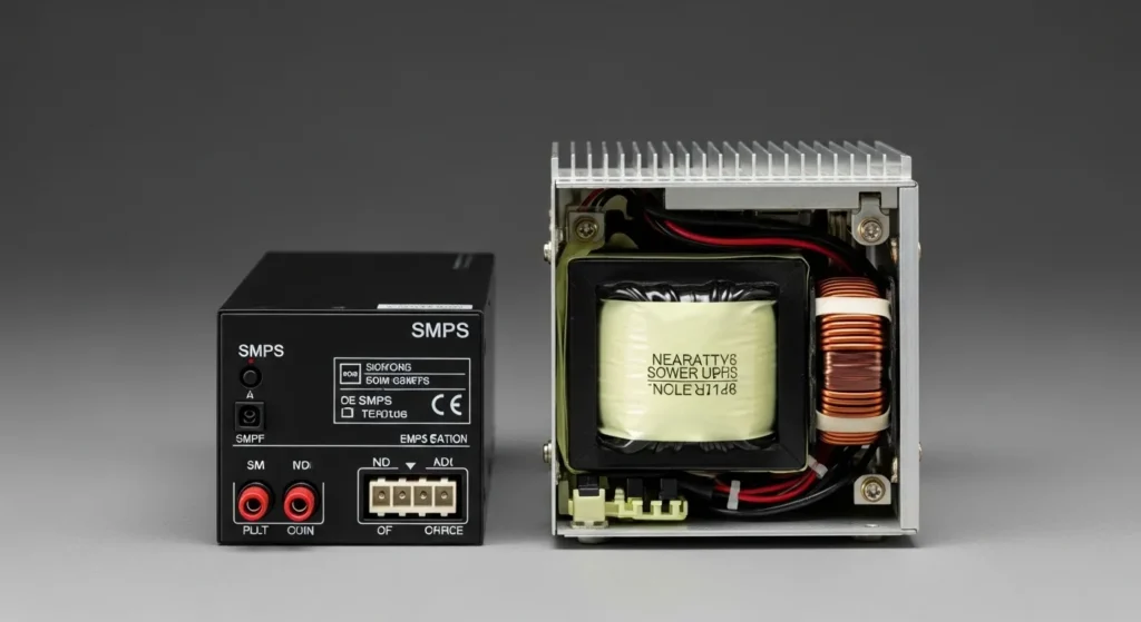
💻 Switched-Mode Power Supplies (SMPS)
SMPS are the dominant power conversion technology in 2026, used in 95%+ of all electronic equipment. Instead of dissipating excess voltage as heat like linear regulators, SMPS rapidly switches the input power on and off (at frequencies from 20 kHz to several MHz) using power MOSFETs or IGBTs, stores energy in inductors and capacitors, and delivers regulated output at dramatically higher efficiency. The high switching frequency enables miniaturisation: a 65 W GaN SMPS is the size of a deck of cards; a 65 W linear supply is the size of a shoebox.
2026 sub-types: Traditional silicon SMPS (flyback, forward, half-bridge, full-bridge topologies 80 PLUS Bronze to Platinum), GaN SMPS (65–240 W ultra-compact chargers, 95–98.5% efficiency), Active-Clamp Flyback (ACF) and LLC resonant topologies for highest efficiency at partial loads, and Digital SMPS with PMBus control for server and telecom applications.
Primary drawback: SMPS generates conducted and radiated EMI from the switching action. High-quality SMPS designs mitigate this with proper EMI filter design, PCB layout, and shielding but for noise-critical analog applications, a linear supply remains preferable.
🔋 Uninterruptible Power Supplies (UPS)
A UPS provides instantaneous battery backup when AC mains power fails, protecting equipment from data loss, unsafe shutdown, or production interruption. The three main UPS architectures serve different needs: Offline (standby) UPS transfers to battery within 10–25 ms on power failure; adequate for home computers and basic office equipment. Line-Interactive UPS regulates voltage fluctuations without switching to battery, transfers to battery in 4–10 ms; suitable for small business servers, networking equipment. Online Double-Conversion UPS continuously converts AC→DC→AC; transfer time is zero (no switching transient); mandatory for data centres, hospitals, and industrial process control.
2026 trend: Lithium-ion UPS (replacing sealed lead-acid) with 10-year battery life, 50% smaller footprint, cloud-based monitoring, and real-time power quality analytics. Lithium-ion UPS units can also function as grid-interactive energy storage during peak demand periods a dual function increasingly mandated by commercial building energy management systems.
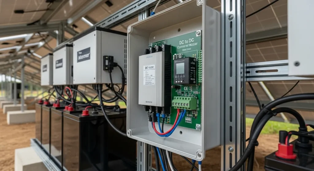
🔌 DC to DC Converters
DC→DC converters change one DC voltage to another without an AC intermediate stage. Three primary topologies: Buck converter (step-down) most common; 12 V→5 V for USB, 48 V→12 V for server boards; efficiencies typically 92–99%. Boost converter (step-up) single Li-ion cell (3.7 V)→5 V for USB output, 12 V→48 V for industrial bus; requires more careful inductor design to manage input current ripple. Buck-Boost converter output can be higher or lower than input; essential for battery-powered systems where battery voltage varies from 4.2 V (full) to 2.7 V (depleted) but output must remain at 3.3 V throughout.
Applications: Solar MPPT chargers (matching panel voltage to battery voltage dynamically), drone power rails (efficient 4S LiPo→5 V logic), automotive (12 V battery→3.3 V/5 V for infotainment), portable medical devices, point-of-load converters on server boards.
⚙️ AC to AC Power Supplies
AC→AC converters transform AC voltage, frequency, or both without conversion to DC. Variable-frequency drives (VFDs): technically AC→DC→AC (with DC bus intermediate), but functionally provide variable-frequency AC output for motor speed control the most common industrial use. Isolation transformers: same frequency, different voltage level; provide galvanic isolation and safety barrier between equipment and mains. Variable AC supplies (Variacs): motor-driven autotransformer providing adjustable voltage 0–270 V AC essential for stress testing equipment and engineering development. Travel voltage adapters: 110 V↔220 V autotransformers for equipment compatibility across grid standards.
🔬 High-Voltage Power Supplies (>1 kV)
High-voltage power supplies (HVPS) generate outputs from 1 kV to 1 MV for specialised applications where standard voltage levels are physically impossible or insufficient. Applications: medical X-ray tubes (30–150 kV), CT scanners, electron microscopes (100–400 kV accelerating voltage), particle accelerators (MeV range), industrial electrostatic precipitators (20–100 kV), laser excitation (CO₂/excimer lasers), and ion implantation for semiconductor manufacturing. Manufacturers like Matsusada Precision design HVPS with arc protection, programmable output, and ultra-stable regulation for these demanding environments. Compliance with IEC 61010 (laboratory equipment) or IEC 60601 (medical) is mandatory.
Linear vs SMPS vs GaN vs Digital: The Definitive Comparison

| Parameter | Linear PSU | Traditional SMPS | GaN SMPS | Digital SMPS (PMBus) |
|---|---|---|---|---|
| Efficiency | 40–60% | 85–94% | 95–98.5% | 94–99% |
| Size & Weight | Very large (mains transformer) | Medium | Ultra-compact | Compact |
| Output Ripple | <1 mV | 50–150 mV | 10–50 mV | Programmable / <20 mV |
| EMI Noise | Essentially zero | Moderate (requires EMI filter) | Low (high-freq, easy to filter) | Low with digital control |
| Cost | Low–Medium (components) | Medium | High (GaN devices premium) | Highest |
| Transient Response | Fast (no feedback delay) | Moderate (feedback loop) | Very fast (MHz switching) | Programmable / adaptive |
| Universal Input | No (requires separate taps) | Yes (100–240 V auto) | Yes | Yes |
| Best For | Audio, lab instruments, RF test | PCs, appliances, industrial | Fast chargers, EVs, thin laptops | Data centres, medical, telecom |
| Primary Standard | IEC 62368-1 | IEC 62368-1, 80 PLUS | DoE Level VI, CoC Tier 2 | PMBus 1.3, IEC 60601-1 |
✅ When to Choose Linear PSU
- High-end audio equipment zero switching noise means zero interference with sensitive phono stages, DACs, and headphone amplifiers
- RF signal generators and spectrum analysers switching noise would corrupt measurements by injecting spurious signals
- Laboratory bench supplies where clean, adjustable, stable voltage is paramount over efficiency
- Precision ADC/DAC reference supplies ripple <100 µV is achievable with good linear design
- Medical patient-connected equipment zero switching transients meet strict IEC 60601-1 leakage current limits more easily
⚠️ When SMPS / GaN Is the Better Choice
- Any battery-powered or portable device 40% efficiency linear PSU would drain battery 2× faster than equivalent SMPS
- Universal-input (international travel) applications linear PSU requires manual voltage selection
- High-power loads (above 50 W) linear PSU heatsink becomes impractical at higher power levels
- Size-constrained designs GaN SMPS at 100+ W/in³ is physically impossible to replicate with linear design
- Cost-sensitive products SMPS components cost less at scale than large mains transformers and heatsinks
Core Engineering Formulas: Efficiency, Ripple & Power Loss
Professional power supply design is governed by three fundamental formulas that determine whether a PSU meets its specifications, safety requirements, and thermal constraints. Every 80 PLUS certification test is based on the efficiency formula; every audio and precision application specifies the ripple formula.
Also: Pin = Pout + Ploss where Ploss = heat dissipated (switching losses in MOSFETs + resistive losses in inductors/transformers)
Example: Pout=450W, Pin=500W → η = 450/500 × 100% = 90% → 80 PLUS Gold level at 50% load
Ploss = 500−450 = 50W dissipated as heat requires heatsinking and thermal management design
f = Ripple frequency: twice the mains frequency for full-wave rectifier (100 Hz for 50 Hz mains; 120 Hz for 60 Hz mains)
C = Filter capacitance after rectifier (F) | This approximation applies when C is large enough that the voltage drop is small
Example: Iload=2A, f=100Hz, C=4,700µF → ΔVripple=2/(100×0.0047)=4.26V pp too high; increase C to 47,000µF → 0.43V pp
For audio (target <1mV ripple): 2A at 100Hz needs C=2/(100×0.001)=20,000µF minimum why linear PSUs use very large capacitor banks
Example: 1000W PSU at 80% efficiency → Ploss = 1000 × (1−0.80) = 200W of heat generation
Same 1000W at 94% efficiency (80 PLUS Titanium) → Ploss = 1000 × (1−0.94) = 60W 70% less heat, smaller heatsink, lower fan noise
Critical for data centres: a rack of 40 × 1000W servers at 80% efficiency generates 8kW of waste heat requiring active cooling; at 94% efficiency, only 2.4kW saving ~5,600W of cooling power per rack
Every watt of Ploss must be dissipated as heat. In a sealed enclosure, this heat accumulates and elevates component temperatures every 10°C increase in semiconductor junction temperature halves the device’s operational lifetime (the Arrhenius reliability equation). A 94% efficient PSU generates 3.3× less heat than an 80% efficient one for the same output power meaning quieter fans, smaller heatsinks, longer component life, and lower data centre cooling costs. For a hyperscale data centre operating 50,000 servers, a 2% efficiency improvement saves millions of dollars annually in electricity alone.
80 PLUS Certification Explained: Bronze to Titanium
The 80 PLUS certification program, established by Ecos Consulting (now Ecova) and widely adopted as an industry benchmark, specifies minimum efficiency requirements at three load levels: 20%, 50%, and 100% of rated output. The 50% load efficiency is most heavily weighted because it represents typical real-world usage a gaming PC under average gaming workload typically operates at 40–60% of PSU capacity. Titanium certification adds a 10% load test, critical for systems with frequent light-load operation.
| Certification | 115V / 10% Load | 115V / 20% Load | 115V / 50% Load | 115V / 100% Load | Typical Applications |
|---|---|---|---|---|---|
| 80 PLUS (White) | N/A | 80% | 80% | 80% | Budget consumer PSUs; minimum acceptable standard |
| 80 PLUS Bronze | N/A | 82% | 85% | 82% | Entry-level gaming, office computers |
| 80 PLUS Silver | N/A | 85% | 88% | 85% | Mid-range builds; relatively uncommon |
| 80 PLUS Gold | N/A | 87% | 90% | 87% | Recommended for gaming PCs, workstations |
| 80 PLUS Platinum | N/A | 90% | 92% | 89% | High-end gaming, professional workstations |
| 80 PLUS Titanium | 90% | 92% | 94% | 91% | AI servers, crypto mining, data centres |
80 PLUS certification tests are conducted at 23°C ambient temperature under standardised conditions. Real-world PSUs inside a loaded PC case may run 10–15°C hotter, reducing efficiency by 1–2%. Additionally, 80 PLUS tests only apply to the AC→DC conversion efficiency they do not measure output ripple, transient response, hold-up time, or EMI performance. A Titanium-certified PSU can still fail these other quality metrics. For a complete PSU quality picture, reference independent reviews from hardware testing labs (Jonny GURU, Tom’s Hardware, GamersNexus) that measure all parameters.
Emerging Technologies: GaN, ACF, ZVS & PMBus Digital Control
Gallium Nitride (GaN) Power Supplies The 2026 Standard
GaN power devices represent the most significant advancement in power conversion since the introduction of silicon MOSFETs. GaN transistors switch at frequencies of 1–10 MHz 10–50× faster than conventional silicon enabling dramatically smaller magnetic components (inductors and transformers scale inversely with switching frequency). At 65 W output, a GaN charger is approximately 60% smaller than an equivalent silicon SMPS. At 140 W, it fits in a palm impossible with silicon technology.
GaN advantages over silicon: switching losses 5× lower (enabling 95–98.5% efficiency), breakdown voltage 10× higher per unit thickness (enabling higher voltage operation with simpler circuit topology), and thermal conductivity suitable for operation at 150°C junction temperature. These properties make GaN the default technology for USB-C PD chargers (65–240 W), laptop power adapters, electric vehicle onboard chargers, and server PSUs in 2026.
Active Clamp Flyback (ACF) & Zero-Voltage Switching (ZVS) Topologies
Traditional flyback converters waste energy in the voltage spike generated when the primary switch turns off (the leakage inductance spike). ACF topology uses a secondary switch and capacitor to recycle this energy, recovering 5–10% additional efficiency and enabling higher switching frequencies. ZVS (Zero-Voltage Switching) ensures the MOSFET switch activates at the moment its drain voltage passes through zero eliminating switching losses at turn-on entirely. Together, ACF and ZVS enable SMPS designs that meet DoE Level VI and CoC Tier 2 efficiency regulations even at 10% of rated load the operating point that previously was the Achilles’ heel of switching supplies.
Digital Power Supplies (PMBus / I²C Controlled)
Modern server, telecom, and high-power LED systems use fully digital PSUs that expose every parameter via PMBus (Power Management Bus), an open-standard I²C derivative. PMBus commands allow host systems to: read real-time input/output voltage, current, and power; programme output voltage with millivolt precision; set current limits and protection thresholds; read temperature sensors and fan speed; receive fault and warning alerts before failures occur; and dynamically scale output voltage for processor speed stepping. This digital control architecture is mandatory for hyperscale data centres and is increasingly specified for Industry 4.0 factory automation where predictive maintenance requires real-time energy monitoring at the component level.
Real-World Case Studies: PC, Lab Bench & Industrial Motor Drive
ATX PC Power Supply: Multi-Rail 80 PLUS Certified SMPS
The standard desktop computer PSU is the most widely deployed example of an AC→DC SMPS. It accepts single-phase AC input (110 V or 230 V, auto-sensing), and outputs five regulated DC rails: +12 V (primary rail for CPU and GPU), +5 V (legacy motherboard logic, USB), +3.3 V (DDR5 memory, NVMe SSDs, modern logic), +5 VSB (standby power for wake-on-LAN and sleep modes), and −12 V (RS-232 signalling, legacy).
The modern ATX 3.0 specification (required for RTX 40/50 series GPUs) adds a 16-pin PCIe 5.0 connector capable of delivering 600 W continuously and handling 150% power spikes (900 W) lasting up to 100 µs a transient load that would collapse an older PSU design not rated for GPU boost behaviour. 80 PLUS Gold certification (≥90% at 50% load) is the minimum recommended for gaming PCs to minimise heat and electricity cost over the system’s operational life.
For a 600 W gaming PC (GPU+CPU TDP), a 750–850 W 80 PLUS Gold PSU provides the optimal headroom (75–88% of capacity at full load). This operating point maximises efficiency, provides transient headroom for peak GPU spikes, and maintains all rail voltages within ATX specification (±5% for +12 V, ±5% for +5 V, ±5% for +3.3 V) under dynamic load conditions.
Bench Power Supply: Linear PSU for Ultra-Low Noise Measurements
A precision electronics development lab specifying a bench PSU for analog circuit characterisation preamplifiers, ADC reference circuits, and sensor conditioning selected a linear benchtop supply over an equivalent SMPS for a specific, measurable reason: the linear supply’s output noise spectral density was 5 µV RMS (10 Hz–10 MHz bandwidth) versus 800 µV RMS for the equivalent SMPS. For measuring a thermocouple output of 40 µV/°C, the SMPS supply noise would introduce 20°C equivalent measurement uncertainty making temperature control impossible. The linear supply’s 5 µV noise floor reduced this uncertainty to 0.125°C within the thermocouple’s specified accuracy.
This single application requirement measurement noise floor justified the linear supply’s weight penalty (4.2 kg vs 0.8 kg for equivalent SMPS) and efficiency penalty (55% vs 90%). Classification: Linear Power Supply with op-amp-controlled output regulation, achieving <500 µV pp ripple at full load across the 0–30 V output range.
CNC Motor Drive PSU: High-Power Industrial SMPS with Active Front End
A CNC machining centre requiring a 300 V DC bus at 15 kW for servo motor drives uses a three-phase AC input, active front-end (AFE) rectifier topology SMPS. The AFE topology (controlled IGBT rectifier, replacing the passive diode bridge) achieves near-unity power factor (PF >0.99), injects <3% total harmonic distortion into the facility’s three-phase supply (meeting IEEE 519-2022 requirements), and enables bidirectional power flow allowing regenerated braking energy from decelerating motors to be returned to the AC grid rather than dissipated as heat in braking resistors.
Classification: High-Power Industrial-Grade SMPS, Active Front-End rectifier, 300 V DC output bus, forced air cooled (IEC 60076-2 thermal testing), EMC compliance per IEC 61000-6-4 (industrial emission standard). Annual energy saved via regenerative braking at this facility: approximately 18,000 kWh equivalent to 7.2 tonnes of CO₂ at regional grid emissions intensity.
Quick Selection Guide: Which Power Supply Do You Need?
| Your Application | Recommended Type | Efficiency | Noise Level | Size | Typical 2026 Cost |
|---|---|---|---|---|---|
| Gaming / Office PC | 80 PLUS Gold/Platinum SMPS (ATX 3.0) | 90–94% | Moderate | Compact | $80–$200 |
| High-End Audio / Precision Lab | Linear (regulated, adjustable) | 50% | Ultra-low <1mV | Large | $150–$600 |
| Phone / Laptop Charging | GaN SMPS (USB-C PD) | 95–98% | Low | Tiny | $25–$80 |
| Server / Hospital Critical | Online Double-Conversion UPS + Regulated SMPS | 92–96% | Low | Medium–Large | $500–$5,000+ |
| Solar / Battery Project | DC→DC Buck/Boost/MPPT | 95–99% | Very low | Small | $10–$150 |
| CNC / Motor Drive | Industrial SMPS (AFE topology) | 96–98% | Low (with EMC filters) | Large | $500–$10,000 |
| Medical Equipment | IEC 60601-1 certified SMPS or Linear | 88–95% | Very low | Medium | $200–$2,000 |
| Arduino / Microcontroller Project | Regulated DC→DC Buck (3.3V/5V) | 92–97% | Low | Tiny | $5–$30 |
Selection Checklist 5 Questions Before Buying
What voltage and current does my device need?
Read the device nameplate or specification sheet. Note input voltage range, polarity (for DC), and peak current (not just average). For computers: add up GPU TDP + CPU TDP + storage/fans and multiply by 1.3–1.5 for headroom.
How sensitive is my application to electrical noise?
Audio, RF, and precision measurement circuits are highly noise-sensitive consider linear PSU or GaN SMPS with excellent output filtering. Digital logic, motor drives, and lighting are noise-tolerant standard SMPS is fine.
Do I need battery backup?
If power loss cannot be tolerated (servers, medical, industrial process control), specify an Online UPS before the PSU. Even home offices with important data benefit from a line-interactive UPS to handle brownouts and spikes.
What efficiency class is required?
Consumer: 80 PLUS Gold minimum. Data centre: Titanium or better. Battery-powered portable: GaN or SiC SMPS for maximum battery life. The efficiency difference between Bronze and Titanium at 1000W load is 100W of waste heat significant at scale or in hot environments.
Are there regulatory or certification requirements?
Consumer/IT: IEC 62368-1 (replaces 60065/60950). Medical: IEC 60601-1, UL 60601-1. Industrial: IEC 61010. Automotive: AEC-Q100/200. Military: MIL-STD-461. Always verify the specific certification on the PSU nameplate or datasheet not just the manufacturer’s marketing claim.
I once helped a client who had specified a $45 unbranded SMPS for their high-precision temperature measurement instrument the instrument would occasionally produce wild temperature readings for 30–60 seconds before stabilising. Scope investigation revealed the SMPS output had 280 mV peak-to-peak ripple at 100 Hz (from the bulk capacitor discharge) plus 40 mV of high-frequency switching noise together creating an equivalent noise input to the ADC of approximately 8°C. Replacing the SMPS with a properly filtered linear regulator supply (total component cost $28) dropped the output ripple to 0.8 mV and completely eliminated the erratic readings. The right supply type for the application is not always the most expensive or most efficient it is the one that meets the specific performance requirements of the load.
12-Step Professional Troubleshooting Guide
Systematic PSU troubleshooting follows a defined diagnostic sequence working from safety through input validation, primary-side analysis, output measurement, and protection verification. Never skip steps or assume the problem each step rules out a failure category before moving to the next.
Safety First Discharge and Isolate
Disconnect mains power. Wait minimum 60 seconds for bulk capacitors to discharge (measure across DC bus with multimeter to verify <10 V before touching primary-side components). Use insulated tools rated for the operating voltage. For high-voltage PSUs (>600 V DC bus), wait longer and use appropriate PPE.
Visual Inspection
Look for: burnt/discoloured components (brown smear, carbon deposits), bulged or leaking electrolytic capacitors (top should be flat, not domed), cracked solder joints at high-stress points (heavy components, thermal cycling areas), evidence of arcing or tracking on PCB, failed MOSFETs (often shattered or physically cracked).
Input Checks AC Side
Verify AC input fuse continuity (common first failure point after surge events). Confirm input voltage at rectifier input matches expected level. Check NTC inrush limiter (should measure cold resistance; failed = 0 Ω or open). Verify EMI filter (X and Y capacitors) continuity shorted X-cap causes persistent blown fuses.
Primary Side Health DC Bus
Measure DC bus voltage after bridge rectifier (should be approximately 1.4× AC input: ~310 V for 220 V AC input, ~155 V for 110 V). Test main switching MOSFET with diode mode check a 0.00 V drain-to-source reading (dead short) confirms catastrophic switch failure, often from thermal runaway or voltage spike. Inspect PWM controller Vcc startup path.
Startup Sequence Verification
Confirm the auxiliary supply (Vcc for PWM controller, typically 12–15 V) comes up correctly. Check startup resistors for correct resistance. Verify auxiliary winding diode and filter capacitor are functional. A failed startup circuit is a common cause of “completely dead” PSUs that have no obviously failed components.
Output Rail Measurement
Measure each output rail under no-load and nominal load conditions. Compare against nameplate specification (ATX: +12 V within ±5%, +5 V within ±5%, +3.3 V within ±5%). Significant droop under load indicates failing output diodes, damaged output inductors, or aged filter capacitors with high ESR.
Ripple and Noise Measurement
Use oscilloscope with a ground spring clip (not flying ground lead) to measure AC ripple on DC output rails. Evaluate at low and high load ripple increases with load. Ripple well above specification (more than 2× rated) strongly suggests aged output capacitors with elevated ESR. Suspect specific capacitor brands known for early failure in the operating temperature range.
Regulation and Feedback Loop
Inspect the optocoupler (check forward current and CTR Current Transfer Ratio with component tester), voltage reference IC (commonly TL431 verify reference voltage accuracy), and feedback resistor divider (verify resistance matches design values). A failed feedback component causes output voltage to drift out of regulation under varying load.
Thermal Performance
Power unit under nominal load, measure heatsink temperatures with contact thermometer or IR camera after 30 minutes. Compare to specification. Confirm fan operates (check fan connector, fan speed control circuit). Look for blocked airflow dust accumulation on fan blades and heatsink fins can increase temperatures by 15–25°C. Reapply thermal interface material on MOSFETs if previously dried out.
Protection Trigger Analysis
Identify which protection feature is activating (OVP: Over-Voltage Protection; UVP: Under-Voltage; OCP: Over-Current; OTP: Over-Temperature). Use a programmable load to incrementally step current from 10% to 110% of rated while monitoring output voltage note exactly where OCP triggers. Verify OCP threshold matches specification. Wrong OCP threshold (too sensitive) causes nuisance trips; too high causes damage to downstream equipment.
Full Load Testing
Apply loads at 10%, 50%, and 100% of rated output using a programmable load or verified resistive load bank. Monitor all output rails simultaneously. Observe transient response when load steps from 50% to 100% output should recover within the specified settling time (typically <1 ms) with <5% voltage deviation. Persistent instability or oscillation during load steps indicates feedback compensation issues.
Isolation and Safety Verification
Verify creepage and clearance distances around the isolation barrier (primary to secondary) have not been compromised by PCB contamination or mechanical damage. Inspect Y-capacitors (line-to-earth filtering) and X-capacitors (line-to-line). Confirm earth continuity on Class I units using a bonding resistance tester (<0.1 Ω primary earth to chassis required by most safety standards).
Advanced Diagnostics: Hold-Up Time & MOSFET Failure Analysis
Measuring Hold-Up Time (Safety Critical for Servers & Medical Devices)
Hold-up time is the duration for which the PSU maintains output voltage within specification after AC input is suddenly lost the standard minimum is ≥17 ms (approximately one full AC cycle at 60 Hz). This window allows connected systems to detect power loss and execute graceful shutdown or switch to UPS. A hold-up time below 10 ms will cause abrupt system resets, data corruption, and filesystem damage in computers even with a UPS present (because the UPS transfer takes 4–10 ms for line-interactive types).
Measurement procedure: Connect the PSU output to its rated load via a programmable load. Connect an oscilloscope Ch1 to the AC mains input (through an isolation transformer for safety), Ch2 to the +12 V DC output rail, and trigger on Ch1 falling edge. Use a relay or solid-state switch to disconnect AC while monitoring. Measure the time from AC loss (Ch1 goes to zero) to the moment DC output falls below 10.8 V (90% of 12 V nominal). A healthy, new PSU will show ≥17 ms hold-up; a PSU with degraded bulk capacitors may show 8–12 ms time to replace before the system in production suffers an unexpected restart.
Diagnosing Primary MOSFET Failure
The primary switching MOSFET (or IGBT in high-power designs) is the most thermally stressed component in an SMPS and the most common cause of catastrophic failure. MOSFET failure modes are typically: drain-source short circuit (thermal runaway junction reaches >150–175°C, intrinsic silicon conductivity rises exponentially, current increases further, creating a destructive positive feedback loop); gate oxide breakdown (from voltage spikes exceeding rated VGS); and open-circuit failure (rare bond wire lifting at high temperatures).
Always disconnect mains power and wait ≥60 seconds before testing primary-side components. The DC bus capacitors store energy at 310–420 V DC sufficient to cause severe electrical burns or cardiac arrest. Verify capacitor voltage is below 10 V with an insulated multimeter before touching any primary-side component. For MOSFET testing: remove the component from the board (or at minimum disconnect the gate drive) before in-circuit measurement to ensure readings are not influenced by other circuit elements.
MOSFET test procedure (out-of-circuit, multimeter in Diode mode):
- Gate to Source: typically measures 0.4–0.7 V (internal body diode) in one direction, OL in reverse normal
- Drain to Source: measures OL in both directions on a healthy enhancement-mode MOSFET (with gate at 0 V) a reading of 0.00 V (short) in either direction confirms catastrophic failure
- Gate to Drain: should measure OL in both directions any conductivity indicates gate oxide breakdown or internal short
🎯 The Bottom Line
Power supply classification is the foundation of every electronics design and purchasing decision. The eight types AC→DC, Regulated, Linear, SMPS, UPS, DC→DC, AC→AC, and High-Voltage each exist because a specific combination of performance requirements (efficiency, noise, voltage range, backup capability, isolation) cannot be met by any other type. The 2026 landscape has simplified one major decision: for any load under 300 W that is not noise-critical, GaN SMPS is the default choice for its unmatched combination of efficiency, size, and universal input capability.
The three formulas govern all design decisions: η = Pout/Pin × 100% tells you the efficiency class and heat generation; ΔVripple ≈ Iload/(f×C) tells you whether your filtering is adequate for the application’s noise sensitivity; Ploss = Pin × (1−η) tells you the heatsinking and thermal management requirements. Master these, and you can specify, evaluate, and troubleshoot any power supply with professional confidence.
The power supply is never glamorous, but it is always critical every electronic failure eventually traces back to either the power supply, the PCB layout, or both. Understanding power supply classification means understanding the foundation of every device that runs on electricity.
⚠️ Safety & Technical Notes
- All work on mains-connected power supplies must be performed with power disconnected and capacitors fully discharged. High-voltage PSUs (>600 V DC bus) require specialised training, PPE, and two-person safety protocols.
- Efficiency figures cited reflect 2026 market conditions at time of publication. Verify current certification data on the 80 PLUS website (clearesult.com/80plus) and manufacturer datasheets before specification.
- IEC and IEEE standards cited are those applicable at time of writing verify current revision status before using in compliance documentation. IEC 62368-1 second edition applies to most new consumer/IT products from 2023.
Frequently Asked Questions
There are 8 core power supply types classified by input/output conversion and application: (1) AC→DC (most common all chargers, PC PSUs, LED drivers); (2) Regulated vs Unregulated (regulation method distinction); (3) Linear (ultra-low noise, 40–60% efficient for audio and lab); (4) SMPS/GaN (85–98.5% efficient, compact for most electronics); (5) UPS (battery backup for servers, hospitals, offices); (6) DC→DC (buck/boost/buck-boost for battery-powered systems, solar, automotive); (7) AC→AC (isolation transformers, VFDs, variacs); (8) High-Voltage (>1 kV) (medical imaging, lasers, particle accelerators). In 2026, GaN SMPS has become the default for loads under 300 W not requiring ultra-low noise.
A linear power supply uses a series-pass transistor operating in its linear (non-switching) region to continuously regulate output voltage. Excess voltage is dissipated as heat efficiency is 40–60%, output ripple is <1 mV, and EMI noise is essentially zero. Ideal for audio, RF, and precision lab applications. An SMPS (Switched-Mode Power Supply) rapidly switches its power transistors on/off (20 kHz–several MHz), stores and releases energy in inductors and capacitors, and regulates output via PWM feedback. Efficiency is 85–98.5% (GaN), size is dramatically smaller, but switching noise must be filtered. The rule: choose linear when noise is critical; choose SMPS when efficiency and size matter.
The power supply efficiency formula is: η = Pout / Pin × 100%, where Pout is the output power delivered to the load (W) and Pin is the input power drawn from the source (W). The difference (Pin − Pout) is Ploss heat dissipated. Example: a 1000 W rated PSU delivering 900 W at 100% load while drawing 967 W from the mains has η = 900/967 × 100% = 93.1% 80 PLUS Platinum level. The 80 PLUS certification measures this efficiency at 20%, 50%, and 100% of rated load; the 50% load value (typical real-world usage) is most important for day-to-day energy cost.
Ripple voltage is the unwanted AC component superimposed on a DC output rail visible as a periodic oscillation on an oscilloscope. It arises from the bulk capacitor’s discharge between rectifier pulses. The approximation formula: ΔVripple ≈ Iload / (f × C), where Iload is load current (A), f is ripple frequency (100 Hz for 50 Hz mains full-wave rectifier; 120 Hz for 60 Hz mains), and C is filter capacitance (F). To achieve <1 mV ripple at 2 A load with 100 Hz ripple frequency: C = 2 / (100 × 0.001) = 20,000 µF minimum which explains why linear PSUs need very large capacitor banks. SMPS achieves low ripple through higher switching frequency (allowing smaller capacitors) plus multiple filtering stages.
Hold-up time is the duration for which a PSU maintains its output voltage within regulation limits after the AC input is suddenly lost the industry standard minimum is ≥17 ms (approximately one AC mains cycle). This time window allows connected systems to detect AC loss and execute controlled shutdown, transfer to UPS, or complete critical write operations. Short hold-up time (<10 ms) indicates degraded bulk capacitors the primary AC-to-DC filter capacitors store the charge that sustains output during the mains interruption. For servers and medical equipment, hold-up time should be measured periodically as part of preventive maintenance a PSU showing <12 ms hold-up has aged capacitors and will cause unexpected system resets even with a 10 ms transfer UPS.
80 PLUS certification measures efficiency at 20%, 50%, and 100% of rated load (Titanium also tests at 10% load). Bronze: ≥82% at 20%, ≥85% at 50%, ≥82% at 100% minimum for modern builds. Gold: ≥87%, ≥90%, ≥87% the recommended minimum for gaming PCs and workstations. Platinum: ≥90%, ≥92%, ≥89% high-end builds. Titanium: ≥90% at 10%, ≥92% at 20%, ≥94% at 50%, ≥91% at 100% mandatory for AI servers, cryptocurrency mining rigs, and data centres where the energy savings over thousands of units justify the premium. At 1000 W output, the difference between Bronze and Titanium is approximately 90 W of waste heat per PSU at data-centre scale, this translates to millions of dollars annually in electricity and cooling costs.
Fully modular PSUs allow all cables (including the 24-pin ATX and EPS 8-pin CPU cables) to be detached when not in use. Semi-modular PSUs attach the essential cables permanently, making peripheral cables removable. Non-modular PSUs have all cables permanently attached. Benefits of modular: reduced cable clutter improves airflow (up to 3–5°C lower case temperatures), makes cable management easier for aesthetics and maintenance, eliminates unused cable bundles that block airflow. Drawback: Each modular connection adds a small resistance (typically 0.5–2 mΩ per connector) and a potential failure point non-modular PSUs have slightly more reliable connections at the cost of flexibility. Recommendation: fully modular for custom builds, small-form-factor cases, and any build where cable management matters.
Follow this 5-step process: (1) Calculate TDP: GPU TDP + CPU TDP + 150 W for storage, fans, and VRMs. Example: RTX 5080 (350 W) + Core Ultra 9 (125 W) + 150 W = 625 W. (2) Add headroom: Multiply by 1.3–1.5 → 625 × 1.35 ≈ 844 W → choose an 850 W unit. (3) Efficiency class: 80 PLUS Gold minimum; Platinum for premium builds and better long-term electricity cost. (4) ATX 3.0 + PCIe 5.0 compliance: Required for RTX 40/50 series graphics cards to handle 150% power spike transients without triggering OCP. (5) Quality indicators: Japanese capacitors (105°C rated), 10-year warranty, independent review scores from GamersNexus/Jonny GURU. Brands with consistent track records: Seasonic, Corsair (AXi/HXi), Super Flower, be quiet! Dark Power.
GaN (Gallium Nitride) transistors offer three fundamental advantages over silicon MOSFETs: (1) Switching speed: GaN switches at 1–10 MHz vs silicon’s 100 kHz–1 MHz enabling magnetic components 10–100× smaller at equivalent filtering performance. (2) Efficiency: GaN switching losses are 5× lower → 95–98.5% efficiency achievable; silicon SMPS peaks at 92–94%. (3) Power density: GaN enables 100+ W/in³ designs a 65 W GaN charger is the size of a large wall plug vs a silicon-based unit the size of a small power brick. The trade-off is cost: GaN transistors are premium-priced, but prices have dropped 60% since 2021 as manufacturing volumes have scaled. By 2026, GaN is the dominant technology for USB-C PD chargers, laptop adapters, and EV onboard chargers, with silicon SMPS remaining for high-power industrial and server applications where proven long-term reliability data is prioritised.
There are two testing methods: (1) Paperclip test (PSU powers on check): With PSU disconnected from motherboard, short the green wire (PS_ON, pin 16) to any black wire (ground) on the 24-pin ATX connector using a paperclip or jumper wire. Plug PSU into mains if the PSU fan spins, it is producing power. This test only verifies startup, not voltage accuracy. (2) Multimeter voltage check: With PSU running (connected to motherboard or with paperclip test), set multimeter to DC voltage. Measure: yellow wire to black (should be +12 V ± 5% = 11.4–12.6 V), red wire to black (+5 V ± 5% = 4.75–5.25 V), orange wire to black (+3.3 V ± 5% = 3.135–3.465 V). Voltages outside these ranges indicate PSU regulation failure. For comprehensive testing, a dedicated PSU tester ($15–$30) checks all rails simultaneously and reports pass/fail with indicators.
Offline (standby) UPS: Normally passes mains power directly to the load; switches to battery via relay when mains fails. Transfer time: 10–25 ms. Lowest cost. Suitable for home computers and non-critical office equipment. Does not regulate voltage fluctuations except during battery operation. Line-Interactive UPS: Uses an autotransformer to regulate voltage (±15–25% tolerance) without switching to battery for minor fluctuations. Transfers to battery in 4–10 ms on power loss. Suitable for small business servers, networking equipment, workstations. Better protection than offline at moderate cost premium. Online Double-Conversion UPS: Continuously converts AC→DC→AC the load always runs from the inverter, never from direct mains. Transfer time is zero (no switching transient). Provides complete isolation from all input power quality issues. Mandatory for data centres, hospitals, and process control systems. Most expensive; inverter runs at full load continuously, generating some heat.
Yes an overheating PSU caused by a manufacturing defect (insufficient heatsinking, wrong thermal interface material, undersized components for rated load, failed temperature protection circuit) is typically covered under warranty. However, overheating caused by user factors is generally excluded: operating in an ambient temperature exceeding the specification (usually 40–50°C), blocked airflow or dust accumulation, overloading beyond the rated wattage, or operating with modified or incorrect cooling. To support a warranty claim: document the symptoms (system shutdowns, burning smell, high surface temperature), verify the operating conditions were within specification, and contact the manufacturer with the PSU model and serial number. Reputable brands (Seasonic, Corsair, be quiet!) typically offer 7–10 year warranties and have established warranty claim processes.
The applicable safety standard depends on the power supply’s intended application: IEC 62368-1 (Audio/Video, Information Technology and Communication Technology Equipment) replaces both IEC 60065 and IEC 60950-1 for most consumer, IT, and AV equipment mandatory for CE marking in the EU, UL certification in North America, and PSE in Japan from 2021 onwards. IEC 60601-1 (Medical Electrical Equipment) applies to PSUs used in medical devices much stricter leakage current limits (<10 µA for patient-connected equipment), mandatory reinforced isolation, and 4,000 V dielectric withstand. IEC 61010 governs laboratory and measurement equipment. MIL-STD-461 applies to military equipment. Always verify that the specific certification (not just “compliance”) is marked on the PSU nameplate by an accredited testing laboratory (UL, TÜV, CSA, DEKRA).
A DC→DC converter changes one DC voltage level to another without an AC intermediate stage. You need one when: (1) You have a DC source (battery, solar panel, vehicle 12 V bus) but your device needs a different DC voltage (3.3 V, 5 V, 48 V); (2) You need efficient voltage stepping at power levels too high for a linear regulator (a linear regulator dropping 12 V→3.3 V at 1 A dissipates 8.7 W as heat a buck converter does the same conversion at 95% efficiency, generating only 0.44 W of heat); (3) Your battery voltage varies during discharge but your device needs a fixed voltage. Common types: Buck (step-down, e.g., 12 V→5 V most common), Boost (step-up, e.g., 3.7 V Li-ion→5 V for USB output), Buck-Boost (output can be above or below input for battery systems), Isolated (flyback) (provides galvanic isolation for medical and safety applications). For Arduino and MCU projects, a simple LM2596 or MP2315 buck converter IC provides 5 V at up to 3 A from a 7–35 V input at 92% efficiency.
📚 Continue Learning on Procirel
📎 Technical References & Standards
- 1Wikipedia Power Supply Classification framework, conversion types, and technical overview of power supply fundamentals [Reference]
- 2Intel Gaming Power Supply Guide PC PSU selection methodology, ATX standards, GPU transient power requirements [Industry Reference]
- 3SlideShare Classification of Power Supply and Its Different Types Educational classification framework reference [Educational Reference]
- 4IEC 62368-1 Audio/Video, Information and Communication Technology Equipment Part 1: Safety Requirements The 2026-current safety standard replacing IEC 60065 and IEC 60950-1 for consumer, IT and AV power supplies [IEC Standard]
- 5IEC 60601-1 Medical Electrical Equipment Part 1: General Requirements for Basic Safety and Essential Performance Leakage current limits, reinforced isolation, and dielectric withstand for medical-grade PSUs [IEC Standard]
- 680 PLUS Program Ecos/Clearesult 80 PLUS Certification Efficiency requirements at 10%, 20%, 50%, 100% load for Bronze through Titanium ratings; certified product database [Industry Certification Program]
- 7IEEE 519-2022 Recommended Practice and Requirements for Harmonic Control in Electric Power Systems THD limits for power supply inputs; relevant to SMPS harmonic injection into facility grid [IEEE Standard]
- 8DoE Energy Star Level VI External Power Supply Efficiency Standards Minimum efficiency requirements at 10%, 25%, 50%, 75%, and 100% of rated output for external power supplies sold in North American markets [Regulatory Standard]
- 9PMBus Specification 1.3 Power Management Bus Protocol Digital communication standard for real-time monitoring and control of power supplies in server, telecom, and industrial applications [Industry Specification]
- 10MDPI (2025) Design and Validation of GaN-Based Single-to-Three-Phase Power Converter Performance benchmarking of GaN PSU efficiency at partial loads; switching frequency advantages vs silicon [Research Paper]