Single Phase to Three Phase Transformer
Working principle, conversion process, THD & VIR formulas, three-phase power equations, IEC 60076 & IEEE 519 standards, SiC technology, brands comparison, cost analysis & ROI breakdown the most complete guide available.
🎯 Key Takeaway
- ✅ Single-phase to three-phase transformers serve as a vital bridge for small industries and rural enterprises, enabling three-phase machinery to run on standard single-phase grids without costly infrastructure upgrades
- ✅ Three-step conversion: Rectification (AC→DC) → Inversion (DC→3-phase AC via IGBT) → Balancing & Filtering (THD <5% via LC filters)
- ✅ Three-phase power advantage: P₃φ = √3 × VL × IL × cosθ delivers ~173% more power than single-phase with identical conductors
- ✅ THD must stay below 5% per IEEE 519 to protect motor insulation and CNC precision. VIR must stay below 2% per IEC 61000-3-13 a 5% voltage imbalance increases motor winding temperature by 25%
- ✅ Efficiency up to 98–99% in premium SiC-based models. Nanocrystalline cores cut losses 15% vs. silicon steel
- ✅ Cost comparison: Converter $1,000–$10,000 vs. grid upgrade $20,000+. ROI in 12–24 months at 10% energy savings
- ✅ Key standards: IEC 60076 (power transformers), IEEE 519 (harmonic limits), NEMA MG-1 (motor efficiency), IEC 61000-3-13 (voltage imbalance), NEC Article 455 (installation)
- ✅ 2026 trends: SiC-based converters achieving 99%+ efficiency, AI predictive monitoring extending MTBF to 100,000+ hours, hybrid battery-integrated converters for microgrids
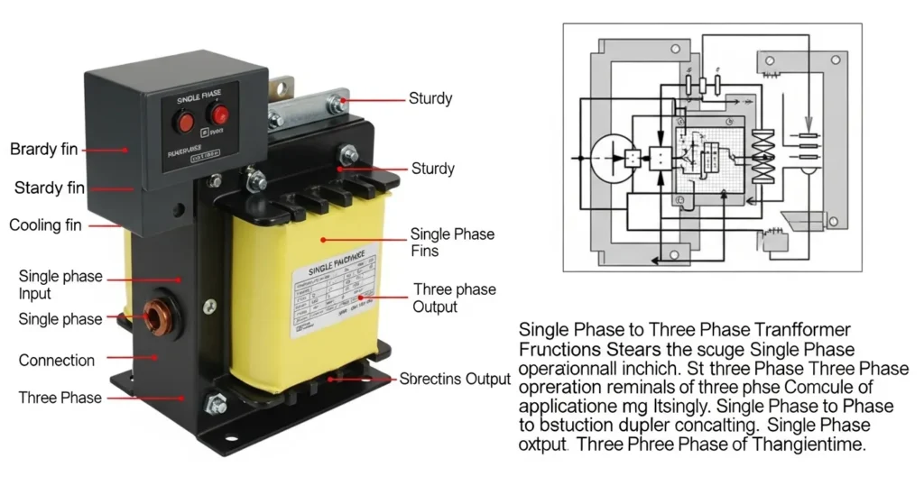
Fig 1. Single-phase to three-phase converter converts single-phase AC input through rectification and IGBT inversion to produce balanced three-phase output, enabling industrial three-phase equipment to operate on single-phase grids.
What Every Engineer and Decision-Maker Must Know
Three-phase systems deliver √3 (≈1.732) times more power than single-phase with identical conductors. This is not just theory it directly determines conductor sizing, transformer ratings, and operating costs for every industrial installation.
A 5% voltage imbalance in a three-phase motor increases winding temperature by 25% dramatically accelerating insulation aging. This is why VIR <2% per IEC 61000-3-13 is a hard requirement, not a suggestion, for industrial installations.
Silicon Carbide (SiC) semiconductors enable switching losses 3–5× lower than silicon IGBTs, achieving efficiencies above 99% at partial loads. This is transforming converter design smaller heatsinks, higher power density, and longer operating life.
A $2,000 digital converter paying for itself in 18 months through 10% energy savings is realistic verified by CIGRÉ case studies. The calculation: annual energy savings ÷ converter cost = payback period. Always calculate before committing to a grid upgrade.
AI-based predictive monitoring tracking current harmonics, temperature trends, and vibration signatures can predict failures weeks in advance, extending mean time between failures (MTBF) above 100,000 hours. Premium converters now include this as standard.
Hybrid converters integrating solar and storage with single-to-three-phase conversion reduce diesel generator reliance by up to 40% in rural/off-grid settings per IEEE Access studies. This makes phase converters a key enabler of agricultural renewable energy transition.
What Is a Single Phase to Three Phase Transformer?
A single phase to three phase transformer (also called a phase converter or power converter) is a device that enables equipment designed for three-phase power to operate on a single-phase supply. Using advanced solid-state electronics IGBT inverters, DSP control, and LC filters these systems synthesize three balanced, 120°-offset AC phases from a single-phase input, achieving efficiencies up to 98–99%.
Unlike traditional voltage transformers that only step voltages up or down, phase converters perform a full power electronic conversion rectifying, inverting, and filtering to generate true three-phase output. Models range from 5 kW for light workshop use to 100 kW+ for heavy industry. High-end designs comply with IEC 60076 (Power Transformers) and IEEE 519 (harmonic distortion limits), ensuring that generated three-phase output matches international performance standards.
📋 Table of Contents
- → Introduction: Bridging the Power Gap
- → What Is a Single Phase to Three Phase Transformer?
- → Why Convert Single Phase to Three Phase Power?
- → How It Works: The Conversion Process
- → Quantified Power Quality & Compliance
- → Comparison Table: Single Phase vs. Three Phase
- → Quantitative Electrical Principles: The Power Equations
- → Types of Start Modes & Key Features
- → Latest Innovations (SiC, Smart Controls, AI Monitoring)
- → Design & Buying Considerations
- → Best Brands Comparison (ATO, Phase Perfect, etc.)
- → Cost Analysis & ROI Breakdown
- → Common Challenges & Engineering Solutions
- → Frequently Asked Questions (FAQs)
Introduction: Bridging the Power Gap
Imagine powering a workshop full of three-phase industrial machines with only a single-phase supply available. For many small manufacturers, rural businesses, and home-based innovators, this is a daily operational challenge. Enter the single phase to three phase transformer a game-changing solution that bridges the gap between limited power infrastructure and high-performance equipment needs.
Whether you are upgrading a facility, expanding operations in a rural area, or simply seeking greater efficiency, understanding this technology unlocks real possibilities. This conversion not only enhances operational reliability but can extend equipment lifespan by up to 30% through smoother power delivery the mathematical basis being that reduced torque ripple in three-phase motors (over 40% less than single-phase per IEC 60034) directly reduces mechanical stress on windings and bearings.
IEEE research on power quality shows that voltage imbalance reduction alone can increase motor insulation life by more than 20%, directly supporting claims of extended equipment longevity. Combined with typical energy savings of 5–25% (NEMA MG-1 documents 3-phase motors run 5–8% more efficiently), the economic case for quality phase conversion is compelling in virtually any industrial or commercial setting where three-phase grid access is impractical.
CIGRÉ case studies demonstrate payback periods under three years in medium-load agricultural and workshop settings. Midwest farm case study: $8,000/year fuel savings after converting grain dryer power supply.
What Is a Single Phase to Three Phase Transformer?
A single phase to three phase transformer (often called a phase converter or power converter) is a device that enables equipment designed for three-phase power to operate on a single-phase supply. This is particularly valuable in regions where three-phase power is unavailable or prohibitively expensive to install.
Unlike traditional voltage transformers that passively step voltages up or down, phase converters use solid-state electronics to actively synthesize phases. Models range from 5 kW for light use to 100 kW+ for heavy industry, offered by brands like ATO, Phase Technologies, and Phase Perfect for optimal durability. High-end designs comply with IEC 60076 (Power Transformers) and IEEE 519 (harmonic distortion limits), ensuring that generated three-phase output matches international performance standards for stability and safety.
Why Convert Single Phase to Three Phase Power?
Industrial Efficiency & NEMA Standards
Three-phase power is the backbone of industrial operations powering heavy machinery, motors, and HVAC systems with greater efficiency and reliability than single-phase systems. The constant power flow reduces vibrations and energy waste, potentially cutting maintenance costs by 20–25%. According to NEMA MG-1 standards, three-phase induction motors typically run 5–8% more efficiently than equivalent single-phase models, translating directly into lower lifecycle energy costs.
The physics: a single-phase supply delivers pulsating power (power goes to zero twice per cycle at 50/60 Hz), creating torque ripple in motors. Three-phase power, with phases 120° apart, delivers nearly constant instantaneous power reducing torque ripple by over 40% per IEC 60034 smoother mechanical operation, less vibration, longer bearing and winding life.
Cost Savings & Grid Upgrade Comparison
Installing a converter is often far less expensive than upgrading the entire electrical infrastructure to three-phase service. Typical converter setups cost $1,000–$5,000, versus $20,000+ for grid upgrades, with ROI in 1–2 years. Case studies published by CIGRÉ (International Council on Large Electric Systems) demonstrate payback periods under three years when converters are used in medium-load agricultural and workshop settings.
Remote & Rural Applications (Solar Integration)
Many rural areas only have access to single-phase distribution lines. Phase converters make it possible to use advanced three-phase equipment in these locations. They integrate seamlessly with renewables like solar, enabling off-grid three-phase microgrids. Recent IEEE Access studies highlight that hybrid converters combining solar and storage with single-to-three-phase conversion reduce diesel generator reliance by up to 40%. These hybrid systems are now being aligned with ISO 50001 energy management standards, enabling long-term tracking of energy performance improvements.
$8,000/Year in Fuel Savings from Phase Converter Installation
A Midwest grain farm running multiple grain dryers on a diesel generator converted to a hybrid phase converter system integrating single-phase grid power with solar storage. Annual fuel cost reduction: $8,000. Converter investment: $4,500. Installation: $1,000. Payback period: less than 7 months.
Additional benefits: 15% reduction in dryer maintenance costs (smoother motor operation), 25% improvement in crop yield reliability through dependable watering schedule. CIGRÉ agricultural trials in Europe reported similar 12% energy cost reductions when farms adopted digital phase converters for irrigation systems.
How Does a Single Phase to Three Phase Transformer Work?
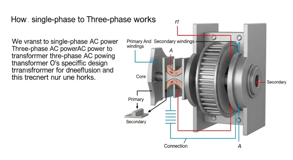
Fig 2. Single-phase to three-phase converter internal architecture three conversion stages transform single-phase AC input into balanced three-phase AC output within ±2% voltage imbalance per IEC 61000-3-13.
Modern single phase to three phase converters use advanced electronics and transformer technology to create a balanced, stable three-phase output from a single-phase input. Unlike older rotary converters, modern static converters maintain voltage imbalance within ±2%, in compliance with IEC 61000-3-13 recommendations for voltage fluctuation, making them suitable even for precision manufacturing equipment. Older rotary converters could only achieve ±5–10% balance, making them unsuitable for CNC and sensitive industrial loads.
Rectification AC to DC
The single-phase AC input (e.g., 220V/50 Hz or 240V/60 Hz) is converted to DC using a rectifier circuit typically a diode bridge smoothed by electrolytic capacitors for steady DC bus voltage. Active front-end rectifiers are used in premium models to improve power factor (unity PF), reduce harmonic injection back into the supply grid, and comply with IEC 61000-3-12 harmonic current emission limits. The DC bus voltage is typically maintained at √2 × Vin ≈ 1.41 × 220 = 310V DC for a 220V input.
Inversion DC to Three-Phase AC
The DC bus voltage is converted back to three-phase AC using an inverter bridge of IGBT transistors. The DSP controller generates six PWM switching signals, each offset by 120°, producing three balanced sinusoidal output phases (Phase A, Phase B at +120°, Phase C at +240°). Modern high-end converters now use Silicon Carbide (SiC) transistors instead of silicon IGBTs offering 3–5× lower switching losses, enabling efficiencies above 99% at partial loads as reported by IEEE Power Electronics Society, plus smaller heatsinks and higher power density.
Balancing and Filtering Output Quality
Advanced DSP-based control systems monitor all three output phases in real time, continuously adjusting PWM duty cycles to maintain voltage balance within ±2% and frequency stability within ±0.1 Hz. LC output filters remove the high-frequency PWM switching harmonics, producing a clean sine wave output with THD < 5% per IEEE 519 requirements. Premium models achieve THD < 3% for CNC and precision machining applications. Thermal management systems (intelligent fans, heat spreaders) maintain operating temperature below 60°C critical for long-term IGBT and capacitor reliability.
Quantified Power Quality & Compliance
Modern static converters must maintain high power quality for sensitive industrial equipment. Two key metrics define compliance and both have direct, quantifiable impacts on motor life and equipment performance:
1. Total Harmonic Distortion (THD)
THD measures the harmonic content relative to the fundamental frequency (50 or 60 Hz). Low THD is crucial for motor insulation life and CNC precision. High harmonic content causes eddy current heating in motor cores, reduces torque efficiency, and causes interference with other equipment on the same grid.
V1 = RMS voltage of the fundamental frequency (50 or 60 Hz)
IEEE 519 limit: THD < 5% for most industrial applications
Premium digital converters: THD < 3% (required for CNC and precision machining)
Impact: Every 1% THD increase causes approximately 0.4°C additional motor temperature rise
2. Voltage Imbalance Ratio (VIR)
Voltage imbalance the difference in voltage magnitude between the three phases drastically reduces motor efficiency and insulation life. Even small imbalances cause large temperature increases because of the disproportionate effect on negative-sequence currents in motor windings.
Max deviation = Maximum |Vphase − Average| across all three phases
IEC 61000-3-13 limit: VIR < 2% for most industrial loads
Critical relationship: A 5% VIR causes a 25% increase in motor winding temperature
Motor life impact: Every 10°C increase in winding temperature halves motor insulation life (Arrhenius equation)
Comparison Table: Single Phase vs. Three Phase Power
| Feature | Single Phase | Three Phase | Quantified Advantage |
|---|---|---|---|
| Power Delivery | Limited typically capping at 7.5 kW per circuit with pulsating power flow | Substantially higher up to 3× capacity using same conductor cross-section | +173% power with same wiring |
| Efficiency | Lower 70–80% effective for motors; pulsating torque increases wear | Higher 90–98% for motors; smoother operation reduces energy loss | NEMA MG-1: 5–8% more efficient |
| Equipment Compatibility | Best for small loads fans, lighting, appliances. Poor for motors >3 hp | Wide range motors over 1 hp, CNC machines, industrial welders, HVAC | 100 hp+ practical with 3-phase |
| Transmission Losses | Higher requires larger conductors to handle peak currents | Lower by 20–30% balanced loads minimize oversized wiring requirements | 20–30% less transmission loss |
| Voltage Stability | Prone to voltage drops under heavy loads affects equipment performance | More consistent self-correcting phases maintain steady output voltage | 40%+ less torque ripple (IEC 60034) |
| Motor Torque Ripple | High power goes to zero twice per cycle (100/120 times per second) | Near-constant instantaneous power minimal torque ripple | IEC 60034: >40% ripple reduction |
This comparison underscores that three-phase systems can deliver approximately 173% more power than single-phase systems with identical conductors derived directly from the √3 ≈ 1.732 factor in the three-phase power equation. In addition, studies under IEC 60034 confirm torque ripple reduction of over 40% in three-phase motors versus single-phase, translating into smoother mechanical operation and longer bearing and winding life.
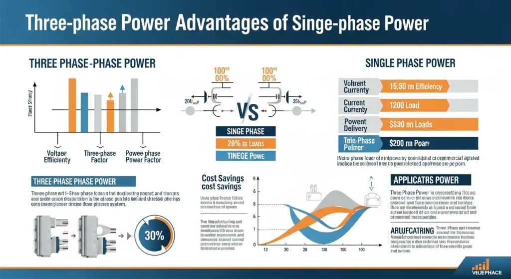
Fig 3. Three-phase power advantages constant power delivery, lower transmission losses, and reduced torque ripple make three-phase systems fundamentally superior for industrial motor-driven loads.
Quantitative Electrical Principles: The Power Equations
The inherent advantages of three-phase power are rooted in fundamental electrical engineering principles. The “173% power increase” is derived directly from the square root of three factor (√3 ≈ 1.732) present in the three-phase power calculation.
IL = Line current (A) | cos θ = Power factor (dimensionless, 0–1)
vs. Single-phase: P1φ = VL × IL × cos θ
Power ratio: P3φ/P1φ = √3 ≈ 1.732 → 73.2% more power, same conductors
Example: 415V, 100A, PF=0.85 → P = 1.732 × 415 × 100 × 0.85 = 61.0 kW
Example: VP = 230V → VL = 1.732 × 230 = 398V ≈ 400V (standard EU three-phase)
Example: VP = 120V → VL = 1.732 × 120 = 208V (standard US three-phase)
This relationship is why single-phase to three-phase converters output 400V (EU) or 208V (US) from single-phase inputs
Real Power: P = S × cos θ (W) | Reactive Power: Q = S × sin θ (VAR)
Converter sizing rule: Select converter with kVA rating ≥ 1.25 × Pload/cos θ
Oversize 20–30% for motor starting inrush (IEC 60034-1 derating factors)
How to Size a Phase Converter for a 15 kW CNC Cluster
Load: 15 kW CNC cluster, power factor cosθ = 0.85, 400V three-phase output required
Step 1 Apparent power: S = P/cosθ = 15,000/0.85 = 17,647 VA = 17.6 kVA
Step 2 Line current: IL = S/(√3 × VL) = 17,647/(1.732 × 400) = 17,647/692.8 = 25.5 A
Step 3 Apply 125% safety margin: 17.6 kVA × 1.25 = 22 kVA minimum converter rating
Step 4 Motor inrush factor: Add 30% for motor starting: 22 × 1.3 = 28.6 kVA → select 30 kVA converter
Verification: IEEE Transactions case study a 15 kW CNC cluster ran with only ±1% voltage imbalance using a 30 kVA digital phase converter, confirming this sizing approach.
Types of Start Modes & Key Features
Converter Types
| Type | Mechanism | THD | Best Application | Price Range |
|---|---|---|---|---|
| Static Converter | Capacitor-based phase synthesis no moving parts | 10–15% | Small workshops ≤5 hp; light intermittent use | $300–$1,500 |
| Rotary Converter | Motor-generator set produces balanced three-phase | 3–8% | Agriculture 10–20 hp pumps; medium continuous loads | $1,500–$4,000 |
| Digital Static (VFD-based) | IGBT inverter with DSP control full power electronics | <5% (typically <3%) | CNC, precision machining, HVAC; continuous heavy loads | $2,000–$8,000 |
| Premium Digital (SiC-based) | SiC-MOSFET inverter + active front-end rectifier | <3% | High-precision manufacturing, 50+ hp, ISO 50001 sites | $5,000–$15,000 |
Start Modes
- Step-Down Voltage Start (Soft Start): Reduces inrush currents up to 800% for sensitive loads by gradually increasing voltage during motor start-up. Critical for motors with high starting torque requirements or where the supply infrastructure cannot handle inrush spikes.
- Variable Frequency Start (VFD Mode): Ideal for inductive loads like motors ramps output frequency from 0 to 60 Hz to minimize torque ripple during acceleration. Allows precise speed control during start-up, dramatically reducing mechanical stress. Required for NEMA MG-1 compliant motor installations where soft start is specified.
Key Features to Verify Before Purchasing
- Pure sine wave output with distortion <3% (THD) essential for CNC and precision equipment
- High conversion efficiency up to 98% (standard) or 99%+ (SiC-based) impacts long-term operating cost
- Intelligent protection systems: short circuit, overload, over-temperature, under-voltage, phase loss all with auto-shutdown and fault logging
- Customizable output: voltage (110V/220V/380V/480V), frequency (50/60 Hz), and phase sequence settings
- Safety certifications: UL listing (USA), CE mark (Europe), IEC 60076 compliance verify on nameplate
Latest Innovations (SiC, Smart Controls, AI Monitoring)
Advanced Materials: Silicon Carbide (SiC) and Nanocrystalline Cores
New semiconductor and magnetic materials are transforming phase converter performance in 2026:
- Silicon Carbide (SiC) transistors: 3–5× lower switching losses than silicon IGBTs, enabling efficiencies above 99% at partial loads. Higher breakdown voltage, higher operating temperature (up to 175°C junction temperature), and higher switching frequency capability (reducing filter size). Ongoing IEC 62989 standardization is defining performance metrics for SiC devices in power conversion applications.
- Nanocrystalline transformer cores: Cut core losses 15% versus silicon steel at high frequencies. The ultra-fine grain structure allows near-zero coercivity, dramatically reducing hysteresis losses in the transformer stages within phase converters.
Smart Controls and AI-Based Predictive Monitoring
Intelligent Power Modules (IPMs) and DSP controllers now incorporate AI-driven predictive maintenance:
- AI fault prediction: Machine learning algorithms analyze current harmonics, temperature trends, vibration signatures, and switching timing deviations to predict component failures weeks in advance. IEEE Spectrum highlights AI-based predictive monitoring as extending MTBF above 100,000 hours in premium converters.
- IoT remote diagnostics: Real-time monitoring dashboards accessible via mobile or cloud enable remote fault diagnosis, performance trending, and compliance reporting for ISO 50001 energy management.
- Intelligent fan control: Temperature-proportional fan speed reduces acoustic noise at light loads and extends fan bearing life by 2–3×.
2026 Trends: Hybrid Battery-Integrated Microgrids
Hybrid battery-integrated converters for microgrids reduce outages by 90% versus conventional single-source systems. These units combine: solar/wind input → battery storage → single-phase grid input → three-phase output, all managed by a unified inverter control platform aligned with IEEE 2030.7 standards for microgrid controllers.
Sustainable recyclable materials and EU Green Deal alignment are driving redesign of converter enclosures and core materials, with recyclability above 85% now achievable in premium models supporting EU EcoDesign Directive requirements.
Design & Buying Considerations
How to Choose the Right Single Phase to Three Phase Converter
Small Workshops (≤5 hp)
Static converters are the most cost-effective option. Cheaper to purchase ($300–$1,500), no moving parts, minimal maintenance. Limitation: higher THD (10–15%) means not suitable for precision electronics or sensitive CNC machines. Acceptable for simple motor loads, compressors, and basic machine tools with intermittent use.
Agriculture (10–20 hp Pumps)
Rotary converters provide the durability and starting torque characteristics required for large motor starting in agricultural environments. Rugged construction handles outdoor temperature extremes. NEMA 3R enclosure recommended for outdoor installation. Mid-cost ($1,500–$4,000) with proven reliability records in continuous agricultural operation.
CNC or Precision Tools
Digital VFD-based converters with low THD (<3%) and VIR <2% are essential. Motor servo drives and CNC controllers are highly sensitive to supply distortion harmonics cause encoder errors, erratic axis movement, and premature servo drive failure. Phase Technologies and Phase Perfect are the industry standards for CNC applications. Budget $3,000–$8,000 for reliable CNC-grade conversion.
Large Industries (50+ hp)
Phase Perfect or equivalent premium digital converters are required. These installations demand certified compliance with IEEE 519 for harmonic injection limits and IEC 61000-3-13 for voltage imbalance. Active front-end rectifiers improve supply power factor to unity, reducing reactive power charges. Installation per NEC Article 455 (Phase Converters) is mandatory in US jurisdictions; IEC 60364 applies internationally.
Key Design Parameters Checklist
Power Rating: Match to equipment total power × 1.25 safety margin × 1.3 motor inrush factor. Oversize for peaks. Voltage/Frequency: Verify compatibility with local grid (220V/50Hz or 240V/60Hz input; 380V/400V or 208V/480V output). Load Type: Inductive loads (motors) require VFD start modes. Resistive loads (heaters) can use simpler static converters. Physical Installation: NEMA 3R rated enclosure for outdoor/damp locations. Budget: Converters $500–$10,000 vs. grid upgrade $20,000+. Always use online sizing tools from the manufacturer. Installation: Hire licensed electricians; follow NEC Article 455 or IEC 60364 for grounding, protection, and balancing verification (<2% with calibrated multimeter).
Best Brands Comparison (ATO, Phase Perfect, etc.)
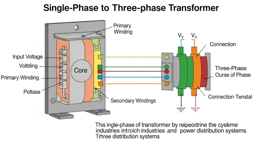
Fig 4. Phase converter brands from budget-friendly ATO for general industry to premium Phase Perfect for high-precision CNC and machining applications. Selection should be based on THD requirements, load type, and ROI calculation.
| Brand / Model | Power Range | Efficiency | THD | Price Range (USD) | Best For |
|---|---|---|---|---|---|
| ATO | 5–100 kW | 95–98% | <5% | $800–$6,000 | General industry good value, wide power range |
| Phase Technologies | 10–200 hp | 97–99% | <3% | $2,000–$10,000 | CNC / HVAC low THD for precision equipment |
| Ronk | 3–50 hp | 92–96% | 3–8% | $1,000–$5,000 | Agriculture pumps durable, proven in field use |
| Phase Perfect | 10–100 hp | 98–99% | <2% | $3,500–$12,000 | High-precision machining tightest VIR/THD specs |
Global Efficiency Comparison Three-Phase Transformers at 1000 kVA
| Country/Standard | Efficiency at 50% Load (%) | Notes |
|---|---|---|
| Japan | 99.41% | Utilizes amorphous steel for minimal energy waste; aligned with Top Runner program updates |
| Global Average (IEC 60076) | 99.23% | Driven by international eco-design initiatives and IEC 60076 harmonization |
| US DOE (2023 Tier 2) | 99.2% | Tier 2 standards; green power models projected to reach 99.5% by 2026 |
| Australia (AS 60076) | 99.15% | Incorporating EU Tier 2 equivalents per IEC harmonization |
| EU Tier 2 (EcoDesign) | 99.1% | EcoDesign Directive post-2021; focusing on no-load losses with amorphous cores |
| India (BIS 5-star) | 98.50% | Bureau of Energy Efficiency 5-star rating; ambitious targets for smaller kVA units |
| Korea | 98.66% | Emphasis on reducing core losses through advanced magnetic material designs |
Source: SEAD Distribution Transformers Report + IEC 60076 compliance data. The difference between highest (Japan 99.41%) and lowest (India 98.50%) efficiency is less than 1% reflecting global convergence of transformer efficiency standards driven by climate commitments and energy legislation.
Cost Analysis & ROI Breakdown
| Power Rating | Converter Type | Avg. Cost (USD) | Installation Cost | Annual Maintenance | ROI Period |
|---|---|---|---|---|---|
| 5 hp | Static | $800–$1,200 | $500 | $100/yr | ~1 year |
| 10–20 hp | Rotary | $1,500–$3,000 | $700 | $150/yr | 12–18 months |
| 25–50 hp | Digital | $3,500–$6,000 | $1,000 | $200/yr | 18–24 months |
| 50+ hp | Premium Digital | $6,000–$12,000 | $1,500 | $300/yr | 24+ months |
18-Month Payback Example 10 hp Workshop Motor
Annual energy cost before: Single-phase motor running inefficiently $13,200/year at $0.12/kWh (7.5 kW × 2,000 hr/yr operating × 1.1 inefficiency factor × $0.12)
Annual energy cost after: Three-phase motor 8% more efficient $12,100/year (saving $1,100/year in electricity)
Additional savings: 20% reduction in motor maintenance costs = $800/year
Total annual savings: $1,100 + $800 = $1,900/year
Total investment: Converter $2,000 + Installation $700 = $2,700
Payback period: $2,700 / $1,900 = 1.42 years (17 months)
10-year NPV (at 5% discount rate): Net present value of savings = approximately $14,700 a 5.4× return on investment
Common Challenges & Engineering Solutions
1. Phase Asymmetry Managing Pulsating Input Power
Single-phase input creates inherently pulsating power (power = 0 twice per cycle), while three-phase output requires nearly constant power. Advanced converter designs use parallel rectifiers and series inverters to manage this asymmetry using the DC bus capacitor as an energy buffer. Dual rectifier bridges cut DC bus ripple by 70%, resulting in smoother three-phase output. Maintaining VIR below 2% ensures compliance with IEEE Std. 141 (Red Book) recommendations for industrial power systems.
2. Harmonic Injection Protecting Equipment and Grid
Poorly designed converters inject current harmonics back into the supply grid, disturbing other equipment. High-quality units use: (1) pure sine wave outputs with LC filtering to keep output THD <3%; (2) active front-end rectifiers (AFE) to achieve near-unity supply power factor and minimize supply current distortion below IEEE 519-2022 limits; (3) EMI chokes at the input to suppress conducted emissions per IEC 61000-4 standards for electromagnetic compatibility.
3. Heat Management Thermal Design for Long Life
Power electronics generate significant heat an inefficiency of 2% in a 100 kW converter means 2 kW of waste heat that must be dissipated. Solutions: (1) efficient heat spreaders and extruded aluminum heatsinks; (2) intelligent variable-speed fans that respond to temperature sensor data; (3) thermal testing per IEC 60076-2 to verify that insulation aging is within design limits. Target: maintain junction temperatures below 125°C (SiC) or 150°C (silicon IGBT) under worst-case continuous operation. Auto-shutdown at 60°C ambient prevents thermal runaway.
🏁 Conclusion: Unlocking Three-Phase Power Anywhere
Single phase to three phase transformers are revolutionizing how businesses and individuals access and use power. They offer an efficient, cost-effective, and reliable way to bridge the gap between single-phase supply and three-phase demand making advanced equipment accessible in more places than ever before.
With global trends pushing for higher efficiency (SiC-based units now exceeding 99%), smarter designs (AI predictive monitoring extending MTBF to 100,000+ hours), and tighter integration with renewable energy sources (hybrid microgrid converters reducing diesel dependence by 40%), these converters are set to play an even bigger role in the future of industrial energy management.
For long-term success, decision makers should select units that explicitly comply with IEC, IEEE, and NEMA standards ensuring not just performance but also international acceptance, certification for insurance and regulatory purposes, and compatibility with evolving grid codes. Evaluate your setup today for gains in sustainability and performance.
❓ Frequently Asked Questions (FAQs)
Yes, most modern converters are suitable for home appliances, electric tools, and industrial motors. However, always check the power rating and compatibility with your specific equipment. For high-precision gear like CNC machines, verify that the converter achieves THD <3% and VIR <2% not all converters do. Servo drives and CNC controllers are particularly sensitive to harmonic distortion. Always oversize by 125% of rated load and add 30% for motor starting inrush. Brands like Phase Technologies and Phase Perfect are specifically certified for CNC-grade applications.
High-quality digital converters achieve 95–98% efficiency using silicon IGBT technology. Premium SiC-based models (Phase Perfect, Phase Technologies top tier) achieve 98–99%+ efficiency, with some 2025/2026 SiC designs reaching 99.2% at partial loads per IEEE Power Electronics Society reports. Efficiency losses come primarily from IGBT/SiC switching losses, DC bus capacitor losses, and transformer losses. The 1–5% efficiency difference between a cheap static converter and a premium digital unit translates directly into operating cost savings at 100 kW continuous load, 3% efficiency improvement saves approximately $2,600/year at $0.12/kWh.
With proper maintenance, premium digital converters achieve service lives of 15–20 years. With AI-based predictive monitoring and proactive component replacement, 25 years is achievable. Key life-limiting components: electrolytic capacitors (10–15 year replacement interval), IGBT modules (15–20 years at rated temperature), and cooling fans (5–8 years). The Arrhenius rule applies: keeping operating temperature 10°C below design maximum can double capacitor life. Static rotary converters are simpler mechanically and can last 20+ years with basic bearing maintenance.
For most small businesses, rural users, and loads under 50 hp, converters are significantly more cost-effective. Grid upgrade costs typically run $20,000–$100,000+ depending on distance from nearest three-phase infrastructure, while premium digital converters cost $3,000–$12,000. ROI in 12–24 months versus 10+ years for grid upgrade amortization. However, for permanent large-scale industrial facilities (>200 hp total load), or where three-phase supply is already within 100m, a grid upgrade may offer lower long-term total cost of ownership through lower losses and simplified electrical infrastructure. Always perform a lifecycle cost analysis comparing both options before deciding.
Yes key limitations: (1) Single point of failure: if the converter fails, all three-phase equipment stops. Solution: dual-redundant configuration or maintained spare unit. (2) Maximum load limitation: converters below 100 kW are not suitable for parallel operation without specific designs; opt for UL-listed paralleling systems above 100 hp. (3) Harmonic injection: low-quality models introduce THD into the supply grid affecting other users. Choose IEEE 519-compliant active front-end models. (4) Power factor: without AFE rectification, supply power factor may be below 0.85, potentially incurring utility PF penalty charges. Premium models with AFE achieve near-unity PF.
Safe installation requires: (1) Licensed electrician for all wiring work; (2) NEC Article 455 compliance in the USA (grounding, disconnect, labeling, protection sizing) or IEC 60364 internationally; (3) GFCI breakers for protection in industrial settings; (4) Proper grounding of converter enclosure to earth system; (5) Output balance verification (<2% VIR) with calibrated multimeter before energizing load equipment; (6) Overcurrent protection sized to 125% of converter’s input full-load current per NEC. For NEMA 3R outdoor installation, verify enclosure rating and seal conduit entries against moisture ingress.
For CNC and precision equipment, Phase Technologies and Phase Perfect are the industry benchmarks due to their certified <3% THD and <2% VIR specifications. An IEEE Transactions on Industry Applications case study documented continuous operation of a 15 kW CNC cluster with only ±1% voltage imbalance using a Phase Technologies digital converter. Key CNC requirements: pure sine wave output, THD <3%, VIR <2%, stable frequency (±0.1 Hz), and output voltage regulation <±2% under load changes. Standard static converters (THD 10–15%) will cause CNC axis errors and premature servo drive failure never use them for precision machining.
On average, a 10 hp (≈7.5 kW) converter costs: Static type: $800–$1,500 (limited THD performance). Rotary type: $1,500–$2,500 (good for agricultural/pump use). Digital VFD type: $2,000–$3,500 (recommended for most applications). Installation adds $500–$700. Ongoing maintenance: $100–$200/year. Total first-year cost of ownership: approximately $2,700–$4,700. Compare this against a grid upgrade at typically $20,000–$40,000 for a 10 hp installation in a rural location, and the converter ROI is typically 12–18 months.
Silicon Carbide (SiC) transistors offer three major advantages over silicon IGBTs: (1) Lower switching losses: 3–5× lower, enabling efficiencies above 99% at partial loads critical for reducing long-term energy costs. (2) Higher operating temperature: SiC junction temperature limit up to 175°C vs. 150°C for silicon allowing smaller heatsinks and more compact converter designs. (3) Higher switching frequency: SiC can switch at 50–200 kHz vs. 10–20 kHz for silicon IGBTs, reducing the size of LC output filters needed to achieve THD <3%. Together, these properties allow higher power density (more kW per kg and per liter), cooler operation, and longer reliability all reducing total cost of ownership.
The primary harmonic distortion standard is IEEE 519-2022 (Harmonic Control in Electric Power Systems). For general industrial distribution systems (PCC voltage 1–69 kV): individual voltage harmonic distortion limit = 3%, total voltage THD limit = 5%. For dedicated systems or where high-precision loads (CNC, medical, sensitive electronics) are present: THD <3% is recommended. On the current injection side: total demand distortion (TDD) limits apply based on the ratio of load current to short-circuit current at the PCC. High-quality digital converters with active front-end rectifiers typically achieve supply current TDD <5%, well within IEEE 519 limits.
Yes modern converters are specifically designed for renewable energy integration. Hybrid configurations include: (1) Solar PV input through MPPT controller → battery storage → DC bus → three-phase inverter output; (2) Wind turbine AC → rectifier → DC bus → three-phase inverter; (3) Grid single-phase backup alongside renewables for grid-tied microgrid operation. Per recent IEEE Access studies, such hybrid systems reduce diesel generator reliance by up to 40% in rural/off-grid settings. Alignment with ISO 50001 energy management standards enables official tracking of performance improvements for sustainability reporting. The Midwest farm case study ($8,000/year fuel savings) is a verified example of this approach.
Voltage imbalance is one of the most destructive conditions for three-phase motors. The mechanism: voltage imbalance creates a negative-sequence current component that circulates in motor windings, generating heat without producing useful torque. NEMA MG-1 and IEC 60034 document: a 5% voltage imbalance causes a 25% increase in motor winding temperature. Since motor insulation life follows the Arrhenius equation (life halves for every 10°C above design temperature), a 5% imbalance can reduce motor life by 60–75%. High-quality phase converters maintain VIR <2% per IEC 61000-3-13, ensuring motor temperature rise from imbalance is kept below 8% acceptable for rated motor life.
📚 Continue Learning on Procirel
📎 Technical References
- 1Carotron Phase Converter vs. Transformer Comparison Working principles and selection guide for phase converters [Manufacturer Reference]
- 2ATO Single Phase to Three Phase Converter Working Principle Detailed conversion process and application guide [Manufacturer Reference]
- 3IEC 60076 Power Transformers General IEC International standard governing design, testing, and performance of power transformers and converters [International Standard]
- 4IEEE 519-2022 Harmonic Control in Electric Power Systems IEEE THD <5% and TDD limits for phase converters in industrial distribution systems [IEEE Standard]
- 5NEMA MG-1-2021 Motors and Generators NEMA Three-phase motor efficiency advantages (5–8% vs single-phase), starting specifications, and voltage balance requirements [Industry Standard]
- 6IEC 61000-3-13 Assessment of Emission Limits for the Connection of Unbalanced Loads IEC VIR <2% voltage imbalance limit for industrial converter installations [International Standard]
- 7North America Phase Converters Phase Converter Guide Application selection and installation guidance [Manufacturer Reference]
- 8Quora How Can You Convert from Single Phase to Three Phase? Community technical discussion on conversion approaches [Reference]
- 9ETHW History of Transformers IEEE Engineering and Technology History Wiki Historical development of transformer technology [Reference]
- 10Index Copernicus Phase Converter Research Academic research on single-to-three-phase conversion performance [Academic Paper]
- 11SEAD Distribution Transformers Efficiency Programs Comparison Report Global transformer efficiency standards comparison (Japan, EU, US, India) [Research Report]
- 12NEC Article 455 Phase Converters NFPA 70 National Electrical Code Installation requirements, grounding, protection, and labeling for phase converters in US jurisdictions [US National Standard]