DC Machine: Types, Working Principle, EMF Equation & Applications
The definitive professional guide from electromagnetic fundamentals and commutator operation to DC motor types, torque equations, standards, predictive maintenance, and real industrial case studies.
🎯 Key Takeaways
- ✅ A DC machine is a bidirectional electromechanical converter it works as a motor (electrical → mechanical) or generator (mechanical → electrical) depending on the energy input
- ✅ The commutator is the defining innovation: it rectifies internal AC into steady DC output and ensures unidirectional torque in motors
- ✅ Five main types: Separately Excited, Shunt, Series, Compound, and Brushless DC (BLDC) each with distinct torque-speed behavior for different applications
- ✅ Core EMF formula: Eb = (P × φ × N × Z) / (60 × A) governs both motor back-EMF and generator output voltage
- ✅ Armature torque: Ta = Ka × φ × Ia torque is directly proportional to flux and armature current
- ✅ Series motors deliver 400–500% starting torque ideal for traction; shunt motors maintain speed regulation below 5% ideal for precision loads
- ✅ Brushless DC motors achieve up to 98% efficiency with no brush maintenance driving EVs, drones, and industrial automation forward
- ✅ Key standards: IEC 60034, NEMA MG1, IEEE 43-2013, IEEE Std 112 these define testing, efficiency classes, and insulation requirements
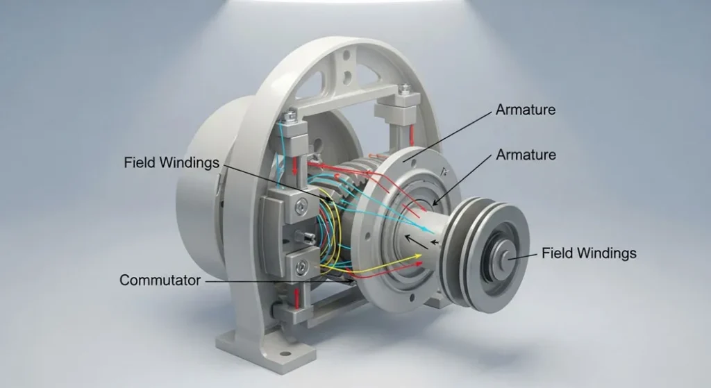
Fig 1. Overview of DC Machine types and their internal winding configurations from traditional brush-commutator designs to modern brushless variants
What Every Engineer Must Know About DC Machines
Without the commutator, the alternating current generated in the armature would produce zero net torque. It mechanically switches current direction to maintain unidirectional rotation a breakthrough that defined modern electrical machines.
A series DC motor at no-load experiences dangerously high speed (theoretically infinite). Always ensure mechanical load is connected before energizing a critical safety rule for cranes, hoists, and railway traction drives.
Per IEEE 43-2013, carbon brushes require inspection every 2,000 operational hours. Worn brushes cause increased contact resistance, commutator sparking, and accelerated copper bar erosion leading to costly rewinding.
Premium efficiency BLDC motors (98%) vs. standard series DC motors (85%) save tens of thousands of dollars over a 20-year operational life. Energy cost dominates total cost of ownership by a factor of 10:1 over purchase price.
Armature current creates its own magnetic field that distorts the main field flux causing brush sparking and uneven commutation. Interpoles and compensating windings are engineering solutions used in large industrial DC drives.
DC motors run as generators during braking converting kinetic energy back into electrical power. EV drivetrains using BLDC motors recover 15–25% of energy during deceleration, extending battery range measurably.
What Is a DC Machine and How Does It Work?
A DC machine is an electromechanical energy converter that uses direct current and electromagnetic interaction to convert between electrical and mechanical energy. When supplied with DC power, it operates as a motor producing rotational torque via the Lorentz force acting on current-carrying armature conductors in a magnetic field (Fleming’s Left-Hand Rule). When driven mechanically, it operates as a generator inducing EMF in its rotating armature conductors via Faraday’s Law of Electromagnetic Induction, with the commutator rectifying the internal AC to produce a steady DC output.
The fundamental distinction from AC machines is mechanical commutation: the commutator-brush assembly ensures that torque production always acts in the same rotational direction, regardless of the alternating nature of the induced currents inside the armature.
📋 Table of Contents
- Introduction to DC Machine
- What Is a DC Machine? Construction & Key Components
- History and Evolution of DC Machines
- How Does a DC Machine Work? Operating Principle
- Types of DC Machines: Shunt, Series, Compound, Brushless
- The EMF Equation and Loss Analysis
- Real-World Applications and Performance Case Studies
- DC Motor Type Comparison Table
- Quantitative Mechanics: Armature Torque Equation
- Industrial Applications of DC Machines
- Advantages and Disadvantages
- DC Machines vs. AC Machines: Complete Comparison
- Buyer’s Guide: How to Choose the Right DC Machine
- Advanced Diagnostics and Predictive Maintenance
- Quantitative Troubleshooting: Faults, Causes & Fixes
- Conclusion
- Industry Standards and Certification
- FAQ: Frequently Asked Questions About DC Machines
Introduction to DC Machine
In today’s world of electric vehicles, precision robotics, and renewable energy systems, the DC machine remains a cornerstone of power conversion technology. Acting as both a motor and a generator in a single mechanical body, it delivers high starting torque, precise speed control, and reliable energy conversion that drive innovation across industries and power the machinery that shapes modern civilization.
From the smooth, instant acceleration of EV drivetrains to the stable power conditioning of renewable energy storage systems, DC machines embody a fundamental principle of electrical engineering: the elegant conversion of energy through electromagnetic interaction. Understanding DC machines is not merely an academic exercise it is an engineering necessity for anyone working in industrial automation, power electronics, traction systems, or robotics.
This guide distills everything engineers, technicians, students, and buyers need to know about DC machines their construction, the key EMF formula, the critical role of the commutator, all motor types and their torque-speed characteristics, loss analysis, compliance with IEEE, IEC, and NEMA standards, buyer selection criteria, and advanced diagnostic protocols. The goal is not just to explain theory but to connect it rigorously to real-world applications, costs, and engineering decisions.
What Is a DC Machine? Construction & Key Components
A DC machine functions as an electromechanical converter that relies on direct current to perform its tasks either transforming electrical input into mechanical output (motor) or converting mechanical energy into electrical power (generator). To illustrate: a DC motor efficiently drives a conveyor system in a busy warehouse, where precise control over speed and torque is essential; a DC generator in a remote solar installation captures rotational energy from a turbine to charge batteries reliably.
What sets DC machines apart from their AC counterparts is their ability to maintain unidirectional current flow, which allows for straightforward adjustments in speed through voltage changes, making them highly adaptable for scenarios demanding accuracy. The commutator a key innovation acts as a rotary switch that ensures the internal alternating currents are rectified into a consistent DC output, a design principle refined in modern industrial practice by manufacturers like ABB and Siemens to meet global reliability standards per IEEE Std 1180. For foundational electromagnetic understanding, refer to Faraday’s law of electromagnetic induction.
Key Construction Components
Yoke (Frame)
The outer structural body, typically cast iron or fabricated steel. It provides the mechanical backbone, houses all internal components, and forms the return path for magnetic flux. In large machines, the yoke is also called the field frame.
Pole Cores & Field Coils
Main poles carry field windings that generate the main magnetic flux. Pole shoes are shaped to distribute flux evenly across the air gap. Interpoles (compoles) are smaller poles positioned between main poles to neutralize armature reaction and improve commutation in larger machines.
Armature Core
Laminated silicon-steel core mounted on the shaft. Slots along the circumference hold the copper armature windings. Lamination (typically 0.35–0.65 mm thick sheets) dramatically reduces eddy current losses compared to a solid iron core.
Commutator
A cylindrical assembly of copper segments separated by mica insulation, mounted on the shaft. In motors, it reverses armature current direction to ensure continuous unidirectional torque. In generators, it rectifies AC armature voltage to DC output. This is the defining component of a classical DC machine.
Carbon Brushes
Spring-loaded graphite blocks that maintain sliding electrical contact with the commutator. They transfer current between the stationary external circuit and the rotating armature. Brush pressure (typically 1.5–2.5 N/cm²) is critical too high causes excessive wear; too low causes sparking.
Bearings & End Frames
Ball bearings (SKF/NSK, IEC 60034-14 compliant) support the shaft and minimize friction losses. End frames (end bells) house the bearings and provide structural rigidity. Bearing condition is a primary predictor of machine lifespan vibration analysis per IEC 60034-14 is the standard diagnostic tool.
History and Evolution of DC Machines
The story of the DC machine is one of the most consequential engineering narratives in history. Its development from a laboratory curiosity to the backbone of global industry spans nearly two centuries and tracks the rise of electrification itself.
| Year | Milestone | Significance |
|---|---|---|
| 1831 | Michael Faraday discovers electromagnetic induction | Establishes the physical law (Faraday’s Law) that makes all electrical machines possible |
| 1832 | Hippolyte Pixii builds the first DC generator | Uses a commutator to rectify alternating current first practical DC machine |
| 1860s | Zénobe Gramme develops the ring armature dynamo | First practical DC generator for industrial power supply |
| 1879 | Werner von Siemens demonstrates the first electric railway | DC series motors power traction beginning of electrified transport |
| 1882 | Edison opens the first commercial DC power station (Pearl Street, NYC) | DC becomes the first public electricity distribution system |
| 1890s | AC wins the “War of Currents” for distribution | DC machines shift from power distribution to industrial drive applications |
| 1960s–80s | Power electronics enable variable-speed DC drives | Thyristor-based SCR drives give DC motors precise speed control in industry |
| 1990s | Brushless DC (BLDC) motors with Hall sensors emerge | Electronic commutation eliminates brushes high efficiency, minimal maintenance |
| 2010s–2026 | BLDC motors dominate EVs, drones, and robotics | Global BLDC market exceeds $11B; permanent magnet designs achieve 98% efficiency |
Today, the classical brush-commutator DC machine remains essential in applications requiring simple, direct speed control printing presses, steel rolling mills, mine hoists, and traction drives where variable voltage control is decades-proven and cost-effective. Simultaneously, brushless DC technology is redefining efficiency standards across electrified transport and automation, demonstrating that the core principle of electromagnetic energy conversion remains as relevant as ever.
How Does a DC Machine Work? Operating Principle
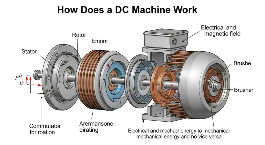
Fig 2. EMF induction in a DC machine: rotating armature conductors cut through the main field flux, inducing voltage per Faraday’s Law. The commutator rectifies the alternating induced EMF to produce steady DC output.
The operation of a DC machine hinges on two foundational laws of electromagnetic physics: Faraday’s Law of Electromagnetic Induction and Fleming’s Rules (Left-Hand for motors, Right-Hand for generators). Understanding these laws at the component level not just as abstract principles is the key to mastering DC machine behavior and diagnosis.
Motor Operation: Lorentz Force → Torque
When DC current flows through the armature windings placed inside a magnetic field (created by the field coils), each current-carrying conductor experiences a mechanical force given by the Lorentz force law: F = B × I × L, where B is the magnetic flux density, I the current, and L the conductor length. The direction of this force (and thus the resulting torque) is determined by Fleming’s Left-Hand Rule the thumb indicates force direction, the index finger the field direction, and the middle finger the current direction.
The commutator’s critical role: as the armature rotates, the current direction in each conductor is reversed at the right moment by the commutator-brush system, ensuring that conductors under the north pole always carry current in the same direction and conductors under the south pole always carry current in the opposite direction. This ensures the force and thus the torque always acts in the same rotational direction, producing continuous unidirectional rotation.
Generator Operation: Faraday’s Law → EMF
When the armature is driven mechanically by a prime mover (turbine, engine, or motor), the armature conductors rotate through the magnetic field. By Faraday’s Law, each conductor cutting through the magnetic flux lines has an EMF induced across it: e = B × L × v, where v is the conductor’s velocity. Since all conductors in one armature winding are connected in series (for wave winding) or in parallel groups (for lap winding), the total EMF is the sum of individual conductor contributions calculated precisely by the EMF equation discussed in Section 6.
The commutator then performs its second critical function: it rectifies the alternating EMF (which reverses polarity each half-revolution) into a unidirectional DC output at the terminals. Without the commutator, a DC machine’s output would be alternating current making it an alternator, not a generator.
Types of DC Machines: All Configurations Explained
DC machines are classified primarily by their field excitation method how the magnetic field is produced and connected relative to the armature circuit. Each configuration produces a fundamentally different torque-speed characteristic, making the choice of type a core engineering decision that determines suitability for a given application.
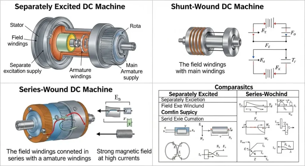
Fig 3. DC machine winding configurations: field coil connections determine whether a machine is shunt, series, compound, or separately excited directly controlling torque-speed characteristics.
1. Separately Excited DC Machine
In a separately excited machine, the field winding is powered from an independent DC source completely separate from the armature supply. This configuration provides the most precise control over magnetic flux, because field current can be adjusted independently of armature current and load conditions. It is the preferred choice in laboratory testing, high-precision drives, and Ward-Leonard speed control systems.
- Speed Control: Excellent both voltage control (below base speed) and field weakening (above base speed)
- Starting Torque: Controllable proportional to armature current at constant flux
- Applications: Research labs, steel rolling mill drives, paper machine drives, Ward-Leonard systems
- Limitation: Requires two separate power supplies increased cost and system complexity
2. Shunt-Wound DC Machine
In a shunt machine, the field winding is connected in parallel (shunt) with the armature. Since the field winding is directly across the full supply voltage (which is relatively constant), the field current and therefore the flux remains nearly constant regardless of load. This produces the defining characteristic of the shunt motor: nearly constant speed across a wide load range.
- Speed Regulation: Excellent typically less than 5% from no-load to full-load
- Starting Torque: Moderate lower than series configuration
- Applications: Lathes, milling machines, fans, centrifugal pumps, conveyors, printing presses all precision constant-speed loads
- Limitation: Cannot handle very high starting torque requirements
3. Series-Wound DC Machine
In a series machine, the field winding is connected in series with the armature. Field current equals armature current, so the magnetic flux is directly proportional to the load current. At starting, both field flux and armature current are high simultaneously producing the highest possible starting torque. As speed increases and current decreases, torque falls rapidly. The torque-speed characteristic is hyperbolic (T ∝ 1/N²).
- Starting Torque: Exceptional 400–500% of rated torque; ideal for moving heavy stationary loads
- Speed Characteristic: Highly variable speed changes dramatically with load; NEVER operate at no-load (risk of runaway)
- Applications: Electric railways, subway traction, hoists, cranes, electric vehicles (traditional traction)
- Critical Safety Rule: Never disconnect the load from a running series motor speed will increase without bound
4. Compound-Wound DC Machine
Compound machines combine both shunt and series field windings on the same poles. This allows the designer to blend the characteristics of both types using the series winding for high starting torque and the shunt winding for speed stability. Two sub-types exist:
- Cumulative Compound: Series and shunt fluxes add together higher starting torque than shunt alone, better speed regulation than series alone. Most common configuration for industrial use.
- Differential Compound: Series flux opposes shunt flux nearly perfectly constant speed (but low starting torque and unstable under heavy loads). Rarely used in practice.
Applications: Elevators, punch presses, rolling mills, compressors, and industrial drives with variable and sudden load changes. The compound motor is often called the “compromise motor” offering 150–200% starting torque margin while maintaining stable running speed.
5. Brushless DC (BLDC) Machine
Brushless DC motors replace the mechanical commutator-brush assembly with electronic commutation using Hall-effect sensors and power transistors (MOSFETs or IGBTs). The permanent magnet rotor’s position is sensed, and the stator windings are energized in sequence to produce continuous rotation. This eliminates all brush-related wear, sparking, and maintenance requirements.
- Efficiency: Up to 98% best of any DC motor type
- Maintenance: Minimal no brushes, no commutator wear, only bearing lubrication required
- Lifespan: 25–35 years in typical operation (vs. 15–25 for brush types)
- Applications: Electric vehicles (Tesla Model 3, BMW i3), drones, robotics, computer disk drives, HVAC fans, medical equipment, industrial servo drives
- Limitation: Higher initial cost; requires sophisticated electronic controller
| Type | Winding Configuration | Key Characteristics | Typical Applications | Torque-Speed Curve |
|---|---|---|---|---|
| Separately Excited | Independent DC field source | Precise control; constant flux; independent adjustment | Labs, robotics, traction drives | Stable Speed |
| Shunt-Wound | Field parallel to armature | Constant speed; low starting torque; <5% regulation | Fans, pumps, lathes, conveyors | Drooping (Stable) |
| Series-Wound | Field in series with armature | 400–500% starting torque; highly variable speed; no-load danger | Cranes, locomotives, hoists | Hyperbolic (High T, Low N) |
| Compound-Wound | Series + shunt (cumulative/differential) | Balanced torque/speed; 150–200% starting torque; overload protection | Elevators, mills, punch presses | Flat with Droop |
| Brushless DC (BLDC) | Electronic commutation; PM rotor | 98% efficiency; no maintenance; 25–35 year lifespan | EVs, drones, robotics, appliances | Efficient Across Ranges |
The EMF Equation and Loss Analysis
Central to evaluating DC machine performance is the electromotive force (EMF) equation, which quantitatively links the machine’s physical parameters to its generated or back EMF. Mastering this equation is essential for motor selection, generator design, and performance prediction.
N = Armature speed (RPM) | Z = Total number of armature conductors
A = Number of parallel paths (A = P for lap winding; A = 2 for wave winding)
Example: 4-pole lap-wound generator, φ = 0.05 Wb, N = 1200 RPM, Z = 200:
Eb = (4 × 0.05 × 1200 × 200) / (60 × 4) = 200 Volts
Understanding the EMF Equation Variables
Each variable in the EMF equation reveals engineering levers for machine design and speed control:
- Flux (φ): Controlled by field current. Increasing flux increases EMF and torque. Reducing flux (field weakening) allows above-base-speed operation in motors.
- Speed (N): For a generator, increasing prime mover speed directly increases output voltage. For a motor, speed adjusts automatically to maintain EMF balance with supply voltage.
- Conductors (Z) and Paths (A): These are fixed at design time. Z/A determines the machine’s electrical “architecture” more conductors → higher voltage at given speed.
For generators: Terminal voltage is back-EMF minus the armature resistive drop
Ra = Armature resistance (Ω) | Ia = Armature current (A)
Loss Analysis: Why Real Machines Are Less Than Perfect
Real-world efficiency is impacted by five categories of loss. Understanding and minimizing these losses is the primary task of machine designers and energy efficiency engineers. Efficiency typically reaches 85–95% under IEC 60034-2-1 standards for conventional brush DC machines, and up to 98% for premium BLDC designs.
| Loss Type | Physical Cause | Mitigation Strategy | Typical % of Total Loss |
|---|---|---|---|
| Copper Losses (I²R) | Resistive heating in armature and field windings increases with I² | Larger conductors, forced cooling, IE3/IE4 design | 40–50% |
| Iron Losses | Hysteresis and eddy currents in laminated armature core | High-grade silicon steel laminations (0.35–0.5mm), grain-oriented steel | 20–30% |
| Mechanical Losses | Bearing friction and windage (fan resistance) | Premium bearings (SKF/NSK), streamlined cooling fans | 10–15% |
| Brush/Commutator Losses | Contact resistance at brush-commutator interface (~1–2V drop per brush) | Premium electrographite brushes, correct spring pressure (1.5–2.5 N/cm²) | 5–10% |
| Stray Load Losses | Flux distortion, leakage flux, non-uniform current distribution | Interpoles, compensating windings, optimized slot design | 5–10% |
We replaced 47 aging brush DC motors on a manufacturing line with premium copper-wound units featuring improved lamination steel. On paper, the efficiency improvement was only 3–5 percentage points. But running 6,000 hours per year at near full load, that seemingly small difference translated to over $22,000 in annual electricity savings across the installation. The capital cost was recovered in 22 months. In continuous-duty applications, loss reduction is a financial decision as much as an engineering one the energy audit always comes first.
Real-World Applications and Performance Case Studies
The selection of a DC machine type is entirely determined by the load’s Speed Regulation requirements and Torque Characteristics. Each type dominates in a specific set of applications where its torque-speed curve provides a natural advantage.
Case Study 1: Series DC Motor in Electric Railway Traction
Series Motor High Starting Torque in Urban Rail
Urban rail systems require enormous starting torque to accelerate heavy train cars from a standstill at every station stop. The series DC motor’s T ∝ I² characteristic means torque is highest at the moment of maximum armature current exactly at startup, when it is needed most.
- Application: Electric Railways, Subway Systems, Hoists, Tower Cranes
- Characteristic: Starting torque reaches 400–500% of rated full-load torque
- Critical Consideration: Series motors are always mechanically coupled to the load never belt-driven, to prevent no-load runaway
- Modern Evolution: Legacy series DC traction motors are being replaced by BLDC motors with regenerative braking in modern metro systems, improving energy recovery by 15–25%
Case Study 2: Shunt DC Motor in Machine Tool Precision
Shunt Motor Constant Speed for CNC Lathes
CNC lathes and milling machines require that the spindle speed remain constant regardless of whether the tool is cutting through dense steel or removing light surface material. Speed fluctuation directly affects surface finish quality and dimensional accuracy.
- Application: Lathes, Milling Machines, Grinders, Fans, Centrifugal Pumps
- Speed Regulation: Typically <5% from no-load to full-load the best of all brush DC motor types
- Siemens 2024 Case Study: DC motor tuning (field weakening optimization + armature voltage profiling) on a precision grinding line achieved 22% energy savings while improving dimensional tolerance by 18%
- Selection Metric: For constant-speed loads, shunt motors with armature voltage control remain cost-competitive against AC + VFD solutions for retrofit applications
Case Study 3: Compound DC Motor for Elevator Drives
Cumulative Compound Motor for Variable Load Handling
Elevator drives experience sudden load changes a full car vs. an empty car represents dramatically different torque requirements. The compound motor’s combination of shunt stability and series starting torque makes it naturally suited to these dynamic load profiles.
- Application: Elevators, Punch Presses, Rolling Mills, Compressors
- Starting Torque: 150–200% margin over running torque handles sudden overloads without stalling
- Speed Stability: Better than series; slightly drooping with load acceptable for elevator duty cycles
- Modern Note: New elevator installations increasingly use BLDC with sophisticated motor controllers, but retrofit of existing compound DC elevator systems remains common in established buildings
DC Motor Type Comparison: Complete Reference Table
This reference table covers all critical selection parameters across all DC motor types. Use it as a first-pass filter when evaluating DC machine options for a new application or system upgrade.
| Parameter | Series | Shunt | Compound (Cumulative) | Sep. Excited | BLDC |
|---|---|---|---|---|---|
| Speed at No-Load | Dangerously High | Stable (~Rated) | Slightly High | Controllable | Controlled by ESC |
| Speed Regulation | Poor (highly variable) | Excellent (<5%) | Good (5–15%) | Excellent | Excellent (electronic) |
| Starting Torque | 400–500% FLT | ~150% FLT | 150–200% FLT | Controllable | High (programmable) |
| Efficiency | 80–88% | 85–92% | 85–91% | 88–93% | 92–98% |
| Maintenance | High (brushes) | Medium (brushes) | Medium (brushes) | Medium (brushes) | Low (bearings only) |
| Speed Control Method | Series resistance / voltage | Armature voltage / field weakening | Armature voltage | Field current + armature voltage | Electronic (PWM/FOC) |
| Best For | Cranes, Railways | Lathes, Fans, Pumps | Elevators, Mills | Labs, Precision Drives | EVs, Drones, Robotics |
| Lifespan | 15–20 years | 15–25 years | 15–22 years | 15–25 years | 25–35 years |
Quantitative Mechanics: Armature Torque Equation
The mechanical power produced by a DC motor is directly related to the Armature Torque (Ta) the force that generates rotation. This is the central equation for sizing a motor for a specific load, whether it’s an elevator hoist, industrial conveyor, or crane drive.
φ = Flux per pole (Wb) | Ia = Armature current (A)
In separately excited and shunt motors: φ is approximately constant → Torque is linearly proportional to Ia
In series motors: φ ∝ Ia → Ta ∝ Ia² (parabolic at low speeds)
Worked Example: Armature Current Sizing
Elevator Hoist Drive: Current and Power Calculation
Scenario: A shunt DC motor is required to produce 100 N·m of torque for an elevator drive. The motor constant and rated flux are such that Ka × φ = 20.
Calculation: Ta = Ka × φ × Ia
→ 100 = 20 × Ia
→ Ia = 5 Amps
Engineering Significance: This 5A figure dictates: (1) the minimum conductor cross-section for armature windings; (2) the minimum current rating for the drive controller and fuses; (3) the heat dissipation requirements for the enclosure (P = I²R = 25 × Ra watts). Undersizing any of these components by even 10% creates a failure-prone system.
The product Eb × Ia = air-gap power this equals mechanical output BEFORE friction/windage losses
Shaft output power = Pmech − Pfriction − Pwindage
Industrial Applications of DC Machines
DC machines stand out for their unique combination of precise control and robust performance. Here are the primary application domains where DC machines in various type configurations provide decisive engineering advantages.
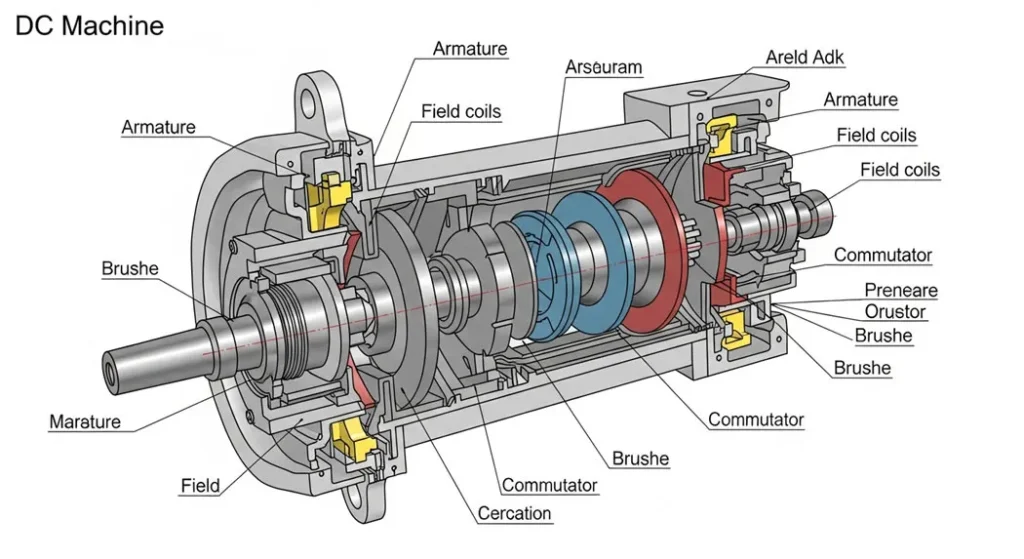
Fig 4. DC machine application domains: from EV traction and renewable energy storage to precision machining, robotics, and industrial hoisting systems.
Electric Vehicles and Traction
In EVs, series and brushless DC motors deliver instant torque from zero speed the defining advantage of DC machines over IC engines. The Tesla Model 3 and BMW i3 use permanent magnet BLDC motors achieving over 90% drivetrain efficiency, with regenerative braking recovering 15–25% of kinetic energy during deceleration. Traditional DC series motors powered urban rail systems for over a century before modern BLDC conversions.
Industrial Automation and Manufacturing
Shunt motors keep precision machine tools (lathes, grinders, milling machines) at constant speed regardless of cutting load variations. Compound motors manage variable loads in steel rolling mills and paper processing lines, handling sudden overloads that would stall a shunt motor or overspeed a series motor.
Renewable Energy Storage
DC generators in solar-wind hybrid installations charge battery banks by converting mechanical turbine rotation into electrical power. The controllable output voltage (via field current adjustment) of separately excited DC generators makes them particularly well-suited for battery charging applications where terminal voltage must be precisely regulated to battery state-of-charge.
Robotics and Precision Control
BLDC motors power robotic joint actuators, drone propulsion systems, and CNC axis drives. Their high power density, precise speed/position control via electronic commutation, and minimal maintenance requirements make them the dominant choice for precision automation. The global BLDC motor market exceeded $11 billion in 2025, driven by EV and robotics growth.
Hoisting and Material Handling
Tower cranes, mine hoists, and port cranes use series or compound DC motors for their high starting torque capability. The speed-torque characteristic of these motors naturally adapts to the varying load of a lifting cycle maximum torque when load is heaviest (at start of lift), automatically reduced torque as load accelerates.
Cost Breakdown: DC Machine Pricing (2026)
| Power Rating | Price Range (USD) | Per-HP Cost | Notes |
|---|---|---|---|
| <5 HP (Small DC motors) | $250–$900 | $200–$300/HP | BLDC: up to $400/HP due to controller |
| 5–50 HP (Medium industrial) | $1,200–$6,000 | $200–$400/HP | Siemens/ABB certified units |
| 50–500 HP (Large industrial) | $8,000–$60,000+ | $250–$500/HP | Custom winding specs; IEC 60034 compliant |
Leading Manufacturers (2026): Siemens (Germany) precision industrial drives; ABB (Switzerland) energy-efficient brushless designs; General Electric (USA) heavy industrial applications; Toshiba (Japan) compact and high-efficiency innovations; WEG (Brazil) cost-effective global products meeting IEC and IEEE standards.
Advantages and Disadvantages of DC Machines
✅ Advantages
- High Starting Torque: Up to 500% of rated torque (series) ideal for heavy load acceleration
- Precise Speed Control: Smooth and wide range adjustment via armature voltage or field weakening superior to AC for many precision applications
- Bidirectional Operation: Simple direction reversal by swapping armature or field polarity
- Easy Regenerative Braking: Natural generator mode during deceleration energy recovery without additional hardware
- No Harmonic Injection: DC operation produces no supply harmonics clean electrical environment
- Established Technology: 150+ years of engineering refinement highly reliable and well-understood failure modes
- Simple Speed Control (low cost): Basic voltage controllers suffice for many applications lower drive cost than AC VFD systems in some cases
❌ Disadvantages
- Brush Maintenance: Carbon brushes require inspection every 2,000 hours sparking, wear, and commutator erosion are ongoing maintenance costs
- Commutator Complexity: Mechanical rectification adds design complexity, manufacturing cost, and a maintenance-intensive component
- EMI Generation: Brush-commutator sparking generates electromagnetic interference problematic in sensitive electronic environments
- Hazardous Area Limitations: Sparking at brushes precludes use in explosive or flammable atmospheres without extensive and expensive ATEX enclosures
- Higher Initial Cost: More expensive than equivalent AC motors in most standard applications above 10 HP
- Efficiency Penalty: Brush contact losses (2–3% of output) inherent in all brush-type DC machines
DC Machines vs. AC Machines: Complete Engineering Comparison
The DC vs. AC machine debate has been ongoing since the 1890s “War of Currents.” Today, both technologies coexist each dominating specific application niches based on their fundamental engineering characteristics. Understanding the trade-offs guides optimal selection. For a deeper dive into AC motor technology, our guide on the Squirrel Cage Induction Motor covers the competing technology in equivalent depth.
| Aspect | DC Machines | AC Machines (Induction) |
|---|---|---|
| Power Source | Direct Current precise control via voltage adjustment | Alternating Current grid-friendly, no conversion needed |
| Commutation | Mechanical (commutator + brushes) maintenance-intensive | None (squirrel cage) maintenance-free rotor |
| Speed Control | Excellent and simple direct voltage/field adjustment | Good with VFD but adds cost and complexity |
| Starting Torque | Very high (series: 500%) natural advantage | Moderate (150–200%) NEMA Design C/D improves this |
| Maintenance | Higher brushes, commutator, periodic overhaul | Lower bearing lubrication only for squirrel cage |
| Efficiency | 85–95% brush; up to 98% BLDC | 88–95% (IE3); 94–97% (IE4) |
| Cost (Initial) | Higher commutator, brush gear, separate DC supply | Lower simpler construction, standardized manufacturing |
| Reversibility | Easy reverse armature or field polarity | Easy with VFD; requires phase sequence change otherwise |
| Hazardous Areas | Limited by brush sparking (ATEX enclosures required) | Preferred no sparking in squirrel cage types |
| Best Application | EVs, traction, precision machine tools, hoists, robotics | Pumps, fans, compressors, conveyors, HVAC |
Buyer’s Guide: How to Choose the Right DC Machine
Choosing the wrong DC machine type or undersizing it is one of the most common and costly engineering mistakes in industrial facilities. This structured selection framework follows the same approach used by ABB and Siemens applications engineers.
Define Load Type and Starting Requirements
Is the load constant speed (fans, pumps → shunt), requires high starting torque (cranes, hoists → series or compound), or needs precise variable speed (machine tools → separately excited or BLDC)? The torque-speed characteristic at startup often determines the motor type before any other parameter.
Calculate Power Rating and Torque Requirements
P = T × ω (Watts). Add 20–25% safety margin above calculated requirement. For variable load applications, use the RMS (root mean square) of the torque cycle, not the peak torque. Power ratings range from 0.5 kW to 500+ kW for industrial DC machines.
Select Voltage Rating and Supply
Common industrial DC voltages: 12V, 24V (light duty), 90V, 180V (standard industrial), 240V, 500V, 600V (heavy industrial). Minimize voltage for safety; maximize for efficiency (lower current → lower I²R losses). Verify that the rectifier/drive can supply the required DC voltage.
Choose Efficiency Class and Enclosure
IE3 minimum for most new installations; IE4 for high-duty-cycle applications. IP54 minimum for industrial environments; IP65 for wet/wash-down areas. TEFC (Totally Enclosed Fan-Cooled) enclosures for dusty or contaminated environments. ATEX certification for hazardous areas avoid brush-type DC if possible in explosive atmospheres.
Verify Standards Compliance and Certification
IEC 60034 (International rotating machines), NEMA MG1 (North American dimensions and performance), IEEE 43-2013 (insulation resistance testing), UL 1004 (safety). Verify CE marking for EU installations. Request the motor’s test certificate showing efficiency at 100%, 75%, and 50% load.
Plan Maintenance Budget and Schedule
Brush-type DC: allocate 2,000-hour inspection intervals, annual insulation resistance testing (IEEE 43-2013), bi-annual vibration analysis (IEC 60034-14). BLDC: bearing lubrication per manufacturer schedule; annual controller diagnostics. Budget 5–10% of initial motor cost per year for maintenance (brush type) or 1–3% (BLDC).
Advanced Diagnostics and Predictive Maintenance Metrics
Modern DC machine maintenance relies on quantitative testing protocols not visual inspection alone to detect failures before they become catastrophic. The two most critical diagnostic disciplines are winding insulation integrity testing and mechanical vibration analysis.
Winding Integrity: Insulation Resistance (IR) Testing
Insulation degradation is the primary cause of DC motor failure. The integrity of winding insulation is measured using a Megohmmeter (Megger), which applies a high DC voltage (500V or 1000V for standard industrial motors) and measures the resulting leakage resistance.
For a 1000V DC machine: IRmin = 1 + 1.0 = 2.0 MΩ minimum
A reading below the minimum indicates moisture contamination or physical insulation damage requiring immediate investigation
Polarization Index (PI) = IR at 10 min / IR at 1 min PI > 2.0 indicates good insulation; PI < 1.5 indicates deterioration
Mechanical Diagnostics: Vibration Analysis
Excessive vibration is a key early indicator of mechanical failure bearing wear, rotor imbalance, shaft misalignment, or loose commutator segments. Vibration is monitored using accelerometers at the bearing housings.
| Vibration Frequency Pattern | Probable Cause | Recommended Action |
|---|---|---|
| High amplitude at 1× RPM | Rotor imbalance or shaft bow | Dynamic balancing or shaft straightening |
| High amplitude at 2× RPM | Shaft misalignment (angular or parallel) | Precision laser alignment, coupling inspection |
| High frequency noise (bearing frequency) | Advanced bearing degradation | Immediate bearing replacement |
| Broadband vibration increase | Loose commutator segments or end-play | Commutator inspection, mica undercutting |
| Vibration at commutator bar frequency | Armature reaction, uneven bar wear | Commutator resurfacing, brush adjustment |
Pro Tip: IoT-Based Predictive Maintenance
Implementing IoT vibration and temperature sensors on critical DC motor installations enables continuous condition monitoring. Per Deloitte industrial IoT studies, predictive maintenance programs reduce unplanned downtime by up to 30% and extend equipment life by 20%. The sensors pay for themselves typically within 18 months on high-value process equipment.Quantitative Troubleshooting: Faults, Causes & Fixes
Diagnosing DC machine faults requires correlating visible symptoms with specific electrical or mechanical measurements. This protocol-based approach eliminates guesswork and prevents misdiagnosis.
Fault 1: Excessive Sparking at the Commutator
Commutator Sparking
Symptom: Bright blue, yellow, or white sparking visible under the brushes during operation. May be accompanied by burnt smell and radio frequency interference.
Root Causes (in diagnostic priority order):
- Brush length below minimum (typically <25% of original length) → increased resistance, arcing
- Incorrect brush spring pressure (outside 1.5–2.5 N/cm² range)
- Commutator bar surface roughness or eccentricity (runout >0.025mm)
- Armature reaction distorted flux from armature current shifts the commutation zone
- High resistance in commutator segments (carbon dust contamination between segments)
Fix Sequence: (1) Measure brush length and spring pressure replace/adjust. (2) Turn commutator on a lathe to restore roundness, then undercut mica. (3) Check interpole connections verify polarity per manufacturer diagram. (4) Clean commutator with dry cloth or commutator stone, never solvent.
Fault 2: Overheating and Burnt Smell
Thermal Overload
Symptom: Motor casing temperature exceeds rated limits (check thermal sensors/IR thermometer). Burnt phenolic/varnish smell. Winding insulation color change visible during inspection.
Root Causes:
- Overloading motor running at >100% FLA continuously
- Excessive ambient temperature (>40°C without derating)
- Blocked cooling ventilation passages carbon dust accumulation
- Supply voltage unbalance (even 5% unbalance causes ~25% additional copper losses)
- High resistance commutator segments localized heating at affected segments
Fix Sequence: (1) Measure armature current and compare to nameplate FLA reduce load or derate motor. (2) Use tachometer to verify rated speed reduced speed at full voltage indicates overloading. (3) Clean cooling passages with compressed air (motor de-energized). (4) Resurface commutator to eliminate high-resistance segments. (5) Megger test winding insulation values below minimum require rewinding.
🏁 Conclusion: The DC Machine in Modern Engineering
DC machines form the backbone of contemporary engineering, enabling seamless energy conversions that power electric transport, renewable energy infrastructure, precision manufacturing, and intelligent automation systems. From the century-old series motor pulling subway trains to the cutting-edge BLDC motor driving a surgical robot, the fundamental electromagnetic principles Faraday’s Law, the Lorentz force, and the elegant mechanical rectification of the commutator remain unchanged and undiminished in relevance.
By understanding the distinct torque-speed characteristics of each DC machine type, mastering the EMF and torque equations, applying IEEE and IEC standards to maintenance protocols, and making informed selections based on the buyer’s guide criteria presented here, engineers and technicians can optimize systems for maximum efficiency, minimum downtime, and lowest total cost of ownership over the machine’s operational life.
For personalized guidance on DC machine selection, drive system design, or maintenance protocol development, reach out to the Procirel engineering team.
Industry Standards and Certification
DC machine performance, safety, and testing protocols are defined by global standards organizations. Compliance ensures interchangeability, reliability, and legal compliance across industries and jurisdictions.
Testing and Performance Standards
| Standard | Organization | Scope | Key Requirement |
|---|---|---|---|
| IEC 60034 Series | IEC (International) | All rotating electrical machines efficiency classes, vibration limits, thermal performance, terminal markings | IE3 minimum efficiency; IEC 60034-14 vibration limits; IEC 60034-2-1 efficiency measurement |
| NEMA MG1 | NEMA (North American) | Motor performance, safety, and physical dimensions ensures physical interchangeability in US/Canadian installations | Frame size standards; torque ratings; temperature rise limits; nameplate data requirements |
| IEEE Std 112 | IEEE | Test procedures for polyphase induction motors establishes rigorous efficiency measurement methods used across all rotating machines | Dynamometer testing; efficiency calculation at multiple load points; loss separation methodology |
| IEEE 43-2013 | IEEE | Insulation resistance testing for rotating machinery defines minimum acceptable IR values and test procedures | IRmin = 1MΩ + (1MΩ × kV rating); Polarization Index >2.0 for new machines |
| UL 1004 | UL (USA) | Electric motor safety dielectric withstand, overload protection, enclosure integrity for North American market | Required for UL listing; safety-critical for US commercial and industrial installations |
❓ Frequently Asked Questions About DC Machines
A DC machine is an electromechanical energy converter that operates bidirectionally: as a motor, it converts DC electrical energy into mechanical torque via the Lorentz force (Fleming’s Left-Hand Rule); as a generator, it transforms mechanical rotation into DC electrical output via electromagnetic induction (Faraday’s Law). Both modes use identical construction the direction of energy flow determines the operating mode. The commutator is the key component that enables both functions, acting as a mechanical rectifier in generator mode and a current-direction reverser in motor mode.
The commutator acts as a mechanical rectifier. In motors, it constantly reverses the current direction in armature windings as the armature rotates, ensuring that conductors under north poles always carry current in one direction and those under south poles in the opposite direction maintaining unidirectional torque. In generators, it rectifies the alternating EMF induced in the rotating armature into a steady DC output at the terminals. Without the commutator, a DC machine’s output would be alternating current. The commutator consists of copper segments separated by mica insulation, riding against spring-loaded carbon brush contacts.
DC motors specifically Series and Brushless DC (BLDC) types provide high starting torque from zero speed (up to 500% of rated capacity for series motors), which is critical for accelerating heavy vehicles from standstill. Additionally, they allow for precise speed control via armature voltage or electronic commutation, and enable regenerative braking running as generators during deceleration to recover 15–25% of kinetic energy back into the battery. BLDC motors in modern EVs achieve over 97% drivetrain efficiency and require minimal maintenance due to the absence of mechanical brush contacts.
The fundamental difference is in their speed-torque characteristics, determined by how field windings connect:
- Shunt Motors: Field windings are in parallel with the armature field current and flux remain nearly constant regardless of load. Result: nearly constant speed (less than 5% regulation from no-load to full-load). Ideal for: lathes, fans, pumps, precision machine tools.
- Series Motors: Field windings are in series with the armature field flux is proportional to armature current. Result: massive starting torque (400–500% FLT) but highly variable speed that drops rapidly as load decreases. NEVER operate at no-load (risk of runaway). Ideal for: cranes, electric railways, hoists.
DC machine efficiency is typically reduced by five loss categories:
- Copper Losses (40–50%): Resistive heating I²R in armature and field windings the largest loss component. Mitigated by larger conductors and improved cooling.
- Iron Losses (20–30%): Hysteresis and eddy currents in the laminated armature core. Mitigated by high-grade silicon steel laminations (0.35mm thickness).
- Mechanical Losses (10–15%): Bearing friction and windage from cooling fan. Mitigated by premium bearings (SKF/NSK) and streamlined fans.
- Brush/Commutator Losses (5–10%): Contact resistance at brush-commutator interface approximately 1–2V drop per brush regardless of load. Mitigated by premium graphite brush compounds.
- Stray Losses (5–10%): Flux leakage, non-uniform current distribution, armature reaction effects. Mitigated by interpoles, compensating windings, and optimized slot geometry.
The generated or back EMF (Eb) of a DC machine is calculated as:
Eb = (P × φ × N × Z) / (60 × A)
Where: P = number of poles | φ = flux per pole (Webers) | N = armature speed (RPM) | Z = total armature conductors | A = number of parallel paths (A = P for lap winding; A = 2 for wave winding). Example: 4-pole lap-wound machine, φ = 0.05 Wb, N = 1200 RPM, Z = 200 → Eb = (4 × 0.05 × 1200 × 200)/(60 × 4) = 200V.
For brush-type DC motors, the essential maintenance schedule includes:
- Every 2,000 hours: Brush length inspection (replace if below 25% original length), spring pressure verification (1.5–2.5 N/cm²), commutator surface inspection for burns or eccentricity
- Annually: Insulation Resistance (IR) testing per IEEE 43-2013 (minimum 1MΩ + 1MΩ/kV rating), commutator resurfacing to eliminate carbon dust and mica build-up, winding cleaning and re-varnishing if contaminated
- Every 6 months: Vibration analysis per IEC 60034-14, bearing condition assessment, cooling passage inspection and cleaning
- BLDC motors: Annual bearing lubrication, electronic controller diagnostics, Hall sensor inspection
Industrial DC machine procurement should prioritize compliance with: IEC 60034 (comprehensive international standard covering efficiency, vibration, thermal performance, and testing for all rotating machines), NEMA MG1 (North American standard for motor performance, safety, and physical dimensions), IEEE 43-2013 (insulation resistance testing procedures and minimum acceptable values), and UL 1004 (electrical motor safety for North American market). Efficiency ratings should be IE3 minimum for most new industrial installations, with IE4 specified for high-duty-cycle applications where energy cost dominates total cost of ownership.
A standard DC machine requires direct current it cannot run directly on AC power from the mains grid. However, it can be integrated into an AC grid using power rectifiers (diode bridges or thyristor-based SCR drives) that convert the AC supply to the required DC voltage. Modern DC drives (such as the ABB DCS880 or Siemens SINAMICS DCM series) perform this AC-to-DC conversion and provide full armature voltage control for variable speed operation. Note: Universal motors (used in hand tools and some household appliances) are a special case that can run on both AC and DC, but they are not equivalent to standard industrial DC machines.
With standardized maintenance protocols, a high-quality industrial DC motor from a major manufacturer (Siemens, ABB, GE) achieves 15–25 years of service life. The primary life-limiting factors are bearing wear (addressed through periodic lubrication and replacement), winding insulation degradation (addressed by preventing overloading, voltage unbalance, and moisture ingress), and commutator wear (addressed through brush maintenance and periodic machining). Brushless DC (BLDC) motors can extend service life to 25–35 years due to the absence of physical brush contacts the only consumable components are the bearings.
📚 Related Articles You Should Read Next
References & Citations
- 1IEEE Std 43-2013 Recommended Practice for Testing Insulation Resistance of Electric Machinery. IEEE Power Engineering Society. [Standard]
- 2IEC 60034-2-1:2014 Rotating Electrical Machines: Standard Methods for Determining Losses and Efficiency. International Electrotechnical Commission. [Standard]
- 3NEMA MG1-2021 Motors and Generators. National Electrical Manufacturers Association. [Standard]
- 4Chapman, S.J. (2012). Electric Machinery Fundamentals, 5th Edition. McGraw-Hill. ISBN 978-0073529547. [Textbook]
- 5ABB (2025). Energy Efficiency in DC Drive Systems: Loss Optimization Whitepaper. ABB Motors and Generators Division. [Industry Report]
- 6Siemens AG (2024). Case Study: 22% Energy Savings Through DC Motor Drive Optimization in Precision Manufacturing. Siemens Digital Industries. [Case Study]
- 7MarketsandMarkets (2025). DC Electric Motor Market Size: Global Forecast to 2030. Report No. EP 7435. [Market Research]
- 8Faraday, M. (1831). “On the induction of electric currents.” Philosophical Transactions of the Royal Society. Wikipedia: Faraday’s Law. [Foundational Science]
- 9Deloitte Insights (2024). Industrial IoT and Predictive Maintenance: ROI Analysis. Deloitte Technology Practice. [Industry Analysis]
- 10IEC 60034-14:2018 Rotating Electrical Machines: Mechanical Vibration of Certain Machines. International Electrotechnical Commission. [Standard]
⚠️ Safety & Technical Disclaimer
The information in this article is provided for educational and informational purposes. All electrical machine installations, maintenance procedures, and modifications must be performed by qualified electrical engineers or licensed electricians in compliance with applicable local electrical codes, NEC/IEC regulations, and manufacturer specifications.
DC machines operate at potentially lethal voltages. Never work on energized equipment. Always follow lockout/tagout (LOTO) procedures per OSHA 29 CFR 1910.147 before performing any maintenance. Never operate a series DC motor without a connected mechanical load. The formulas and calculations in this guide are for estimation purposes always verify against specific motor datasheets and conduct professional engineering analysis before implementation.