Voltage Divider Circuit: Formula, Loading Effect, Thevenin Equivalent & AC Analysis
The definitive professional guide from the basic Vout formula and Ohm’s Law derivation to the loading effect, Thevenin equivalent model, AC impedance analysis, RC filters, potentiometers, CVT high-voltage systems and IEC 60063 resistor standards.
🎯 Key Takeaways
- ✅ Core formula: Vout = Vin × R2 / (R1 + R2) derived from Ohm’s Law and Kirchhoff’s Voltage Law; applies only when no load draws current from Vout
- ✅ Loading effect is the #1 beginner mistake connecting any load RL in parallel with R2 reduces Vout; RL must be ≥ 10× R2 for <10% error
- ✅ Thevenin equivalent: VTH = unloaded Vout; RTH = R1 ∥ R2 the professional model for predicting actual output with any load attached
- ✅ For AC signals, replace R with complex impedance Z; a resistor + capacitor forms an RC low-pass filter with cutoff fc = 1/(2πRC)
- ✅ Potentiometers are mechanically adjustable voltage dividers used for calibration, volume controls, and position sensors
- ✅ High-voltage systems use Capacitive Voltage Transformers (CVT) a capacitive divider governed by IEEE Std C57.13 for safe kV-level measurement
- ✅ Resistor standard values are defined by IEC 60063 E-series E12 for ±10% tolerance, E24 for ±5%, E96 for ±1% always choose from the nearest standard value

What Every Engineer Must Know About Voltage Dividers
The classic Vout = Vin × R₂/(R₁+R₂) assumes zero current flows out of Vout. In practice, every connected circuit draws current invalidating the simple formula unless RL ≥ 10×R₂.
A high RTH = R₁∥R₂ makes Vout a high-impedance node extremely susceptible to EMI and noise pickup. Keeping R values small lowers RTH but increases quiescent current waste.
Every potentiometer (volume knob, trimmer) is a voltage divider with a mechanically adjustable wiper. The ratio R₂/(R₁+R₂) changes continuously as the wiper moves not a separate circuit concept.
Replace R with complex impedance Z = R + jωL + 1/(jωC). The output ratio changes with frequency this is exactly how RC and LC filters work. Every passive filter is a frequency-selective voltage divider.
A voltage divider continuously dissipates power as heat: P = Vin² / (R₁ + R₂). For battery-powered designs, use high-resistance values (100 kΩ+) or a linear voltage regulator instead.
At 100 kV+, resistive dividers would dissipate megawatts. Capacitive Voltage Transformers (CVT) use series capacitors to step down voltage with negligible power loss governed by IEEE Std C57.13.
What Is a Voltage Divider and How Does It Work?
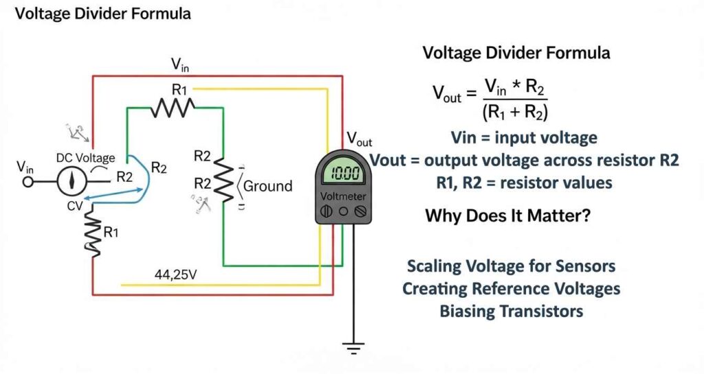
A voltage divider is a passive linear circuit that uses two or more impedances in series to produce an output voltage (Vout) that is a fraction of the input voltage (Vin). It is one of the most fundamental building blocks in circuit design, applying directly from Ohm’s Law and Kirchhoff’s Voltage Law. In its simplest form, two resistors R₁ and R₂ are connected in series across Vin; the output is measured across R₂. Because the same current flows through both resistors (series circuit), the voltage across each is proportional to its resistance a relationship described by the voltage divider rule.
The formula Vout = Vin × R₂/(R₁+R₂) assumes an ideal, unloaded condition. In real circuits, the connected load modifies the effective value of R₂ through a parallel combination reducing Vout below the calculated value. This loading effect, and the Thevenin equivalent model that quantifies it, are the professional engineer’s essential extensions of the basic formula. The DigiKey voltage divider calculator can verify quick designs, but understanding the underlying mathematics is essential for reliable circuit work.
Table of Contents
- The Voltage Divider Formula: Derivation from First Principles
- Step-by-Step Worked Examples with Real Scenarios
- The Loading Effect: The #1 Beginner Mistake Explained
- Thevenin Equivalent Model: Professional Analysis for Loaded Dividers
- AC Voltage Dividers: Complex Impedance & RC Filter Analysis
- Current Divider vs Voltage Divider: When to Use Each
- Practical Applications: Sensors, ADCs, Level Shifting & Audio
- Potentiometers: The Adjustable Voltage Divider
- High-Voltage Systems: CVT Dividers & IEEE Std C57.13
- Resistor Selection: IEC 60063 E-Series, Tolerances & Power Rating
- Troubleshooting: Common Failures & Practical Fixes
- Frequently Asked Questions
The Voltage Divider Formula: Derivation from First Principles
The voltage divider formula is not an empirical rule it is a direct mathematical consequence of two fundamental laws of circuit theory. Understanding the derivation ensures you know exactly when the formula applies and when it breaks down.
Step 1: Kirchhoff’s Voltage Law (KVL)
In a series circuit, the sum of voltage drops across all elements equals the source voltage. With R₁ and R₂ in series across Vin, and denoting the current flowing through both as I:
Vin = VR1 + VR2 = I·R₁ + I·R₂ = I(R₁ + R₂)
Step 2: Solve for Current (Ohm’s Law)
I = Vin / (R₁ + R₂)
Step 3: Calculate Vout Across R₂
Vout is the voltage across R₂, which by Ohm’s Law equals I × R₂. Substituting the expression for I:
Key insight: The ratio R₂/(R₁+R₂) is always between 0 and 1 Vout is always less than or equal to Vin
Symmetry check: When R₁ = R₂, Vout = Vin/2 exactly half, as expected
Critical assumption: No current flows out of Vout the load draws zero current
The formula above is mathematically exact but only under one critical condition: the output terminal draws zero current. The moment you connect any circuit (a microcontroller ADC pin, a transistor base, another circuit) to Vout, current flows out of the divider, the effective value of R₂ changes, and the formula gives the wrong answer. This is the loading effect covered in detail in Section 3. According to the voltage divider circuit analysis from Study.com, ignoring loading is the single most common source of error in student and hobbyist circuit designs.
Step-by-Step Worked Examples with Real Scenarios
Example 1: Sensor Supply 12V to 4V
A motion sensor requires exactly 4V from a 12V automotive supply. Choose R₁ = 8 kΩ and R₂ = 4 kΩ:
Total resistance
Rtotal = R₁ + R₂ = 8 kΩ + 4 kΩ = 12 kΩ
Series current
I = Vin / Rtotal = 12V / 12,000Ω = 1 mA
Output voltage
Vout = Vin × R₂/(R₁+R₂) = 12V × (4/12) = 4V ✓
Power dissipation check
P = I² × Rtotal = (0.001)² × 12,000 = 12 mW well within standard ¼W (250 mW) resistor rating
Example 2: Jetson Nano / Arduino 5V to 2V Signal Conditioning
A 5V digital signal must be scaled to 2V for a 2V-tolerant ADC input. Choose R₁ = 3 kΩ, R₂ = 2 kΩ:
Verification: VR1 = 1mA × 3kΩ = 3V; VR2 = 1mA × 2kΩ = 2V; 3V + 2V = 5V = Vin ✓ (KVL confirmed)
Example 3: Home Automation 15V to 5V for Motion Sensor
Vin = 15V, target Vout = 5V. Choose R₁ = 10 kΩ, R₂ = 5 kΩ:
- Total resistance: 10 kΩ + 5 kΩ = 15 kΩ
- Current: I = 15V / 15,000Ω = 1 mA
- Vout = 15V × (5/15) = 5V ✓
- Power in R₂: P = (1 mA)² × 5 kΩ = 5 mW safe for standard resistors
Quick Reference Table: Common Divider Setups for 12V Input
| R₁ (kΩ) | R₂ (kΩ) | Vout (V) | I (mA) | Power (mW) | Use Case |
|---|---|---|---|---|---|
| 6 | 6 | 6.0 | 1.0 | 12 | 6V relay coil, mid-rail reference |
| 8 | 4 | 4.0 | 1.0 | 12 | Sensor for Jetson Nano, ADC input |
| 3 | 9 | 9.0 | 1.0 | 12 | LED driver bias, transistor base |
| 10 | 5 | 4.0 | 0.8 | 9.6 | Microcontroller input scaling |
| 22 | 10 | 3.75 | 0.375 | 4.5 | Low-power battery applications |
| 100 | 50 | 4.0 | 0.08 | 0.96 | High-impedance reference (minimal current draw) |
Standard carbon film resistors have ±5% (E24 series) or ±10% (E12 series) tolerance. In a 12V divider with R₁ = 8 kΩ ±5% and R₂ = 4 kΩ ±5%, the worst-case Vout variation is: minimum (R₁ max, R₂ min): Vout = 12 × 3.8/(8.4+3.8) = 3.74V; maximum (R₁ min, R₂ max): Vout = 12 × 4.2/(7.6+4.2) = 4.27V. That is ±6.7% error from tolerance alone. For precision applications, use ±1% metal film resistors (E96 series) to reduce tolerance error to ±2% or less.
The Loading Effect: The #1 Beginner Mistake Explained
The loading effect is the single most important concept that separates a working voltage divider design from a broken one. Every textbook presents the simple formula; very few emphasise that this formula becomes incorrect the moment you connect a real circuit to the output.
What Happens When a Load is Connected?
When you connect a load resistance RL across the output of a voltage divider (across R₂), RL appears in parallel with R₂. The parallel combination has a lower resistance than R₂ alone always. This reduces the effective bottom resistance of the divider, pulling Vout down below the calculated value.
Then substitute R2(eff) into the standard formula: Vout,loaded = Vin × R2(eff) / (R₁ + R2(eff))
Key observation: R2(eff) is always < R₂ → Vout,loaded is always < Vout,unloaded
Quantified Loading Error Worked Example
Design target: Vout = 4V from 12V with R₁ = 8 kΩ, R₂ = 4 kΩ. Load RL = 10 kΩ connected to output:
- R2(eff) = (4 kΩ × 10 kΩ) / (4 kΩ + 10 kΩ) = 40,000 / 14,000 = 2.857 kΩ
- Vout,loaded = 12V × 2.857 / (8 + 2.857) = 12V × 0.263 = 3.16V instead of the expected 4V
- Loading error = (4V − 3.16V) / 4V × 100% = 21% error
| RL / R₂ Ratio | RL (kΩ) for R₂=4kΩ | Vout,loaded | Loading Error | Verdict |
|---|---|---|---|---|
| 1× R₂ | 4 kΩ | 2.67V | 33% | Unacceptable |
| 5× R₂ | 20 kΩ | 3.53V | 12% | Unacceptable |
| 10× R₂ | 40 kΩ | 3.64V | 9% | Marginal |
| 20× R₂ | 80 kΩ | 3.81V | 4.8% | Acceptable for non-precision |
| 100× R₂ | 400 kΩ | 3.96V | 1% | Good |
| ∞ (no load) | Open circuit | 4.00V | 0% | Perfect (theory only) |
Early in my career I designed a 5V-to-3.3V divider for a sensor interface using R₁ = 2.2 kΩ and R₂ = 3.3 kΩ. On the bench with no load, I measured exactly 3.3V. Connected to the microcontroller ADC pin (which has an internal input impedance of approximately 10 kΩ), the voltage dropped to 2.8V the ADC was interpreting full-scale inputs as only 85% of the expected range. Every sensor reading was systematically wrong. I had ignored the loading rule. The fix was switching to 22 kΩ and 33 kΩ (10× higher values, same ratio) the ADC’s 10 kΩ input impedance became 30% of R₂ instead of 300%, reducing loading error to under 2%. Lesson learned once, never forgotten: always check your load impedance against your divider resistors before building.
Thevenin Equivalent Model: Professional Analysis for Loaded Dividers
The Thevenin theorem is the professional engineer’s tool for analysing any two-terminal circuit including a loaded voltage divider regardless of how complex the attached load becomes. By replacing the entire voltage divider with its Thevenin equivalent (a single voltage source VTH in series with a single resistance RTH), you reduce any loaded divider problem to a trivially simple two-element circuit.
Calculating VTH and RTH
With Vin shorted: R₁ and R₂ are now in parallel (both connected between the output node and ground/supply respectively, which both become the same node when Vin is shorted).
Example: R₁ = 8 kΩ, R₂ = 4 kΩ → RTH = (8 × 4)/(8 + 4) = 32/12 = 2.667 kΩ
Example: VTH=4V, RTH=2.667kΩ, RL=10kΩ → Vout=4×10/(2.667+10)=4×0.789=3.16V ✓ (matches Section 3 calculation)
Why RTH Matters Beyond Loading: Noise and Stability
RTH is not just a loading analysis tool it has critical implications for the quality of the output voltage as a reference or supply rail:
- Noise susceptibility: A high RTH makes Vout a high-impedance node. Any capacitively-coupled interference (from nearby switching circuits, motor drives, or mains fields) appears as noise on Vout. A 10 kΩ RTH with 1 pF stray capacitance creates a noise time constant τ = RTH×C = 10 ns sufficient to cause ADC sampling errors in fast-switching environments. Adding a 100 nF bypass capacitor from Vout to ground creates an RC filter with fc = 1/(2π×10kΩ×100nF) ≈ 160 Hz, which suppresses most EMI.
- Transient response: A large RTH combined with the capacitance of attached circuit inputs creates a slow RC time constant Vout recovers slowly from transient load changes. For fast ADC applications, keep RTH below 1 kΩ or add a unity-gain buffer op-amp (voltage follower) to reduce output impedance to near zero.
- The engineering trade-off: Lower R₁ and R₂ values → lower RTH → better stability and noise immunity. But lower values also increase quiescent current (P = Vin²/(R₁+R₂)) and waste battery power. The design optimum balances these competing requirements for the specific application.
Why the Simple Formula Often Fails in Practice
The voltage divider equation is mathematically perfect but its practical application leads to errors unless two non-textbook factors are considered. The first is the Loading Effect the formula assumes R₂ is connected to infinite resistance. Any real load acts as a parallel resistor, dragging Vout below the calculated value. The rule: Rload must be at least 10× R₂ for under 10% error; 100× R₂ for under 1% error.
The second is Thevenin Equivalence. For serious design, think of the voltage divider as a Thevenin equivalent circuit. The Thevenin resistance RTH = R₁∥R₂ is the output impedance it determines noise susceptibility, transient response, and stability. A high RTH makes Vout jittery and noise-prone. A low RTH wastes power. The real engineering challenge is choosing the largest R values that still maintain a low enough RTH to filter noise and respond quickly to load changes this is the fundamental design trade-off that textbooks rarely address quantitatively.
For a divider used as a reference or bias voltage: RTH should be ≤ 10% of the load impedance. For ADC input conditioning: RTH should be ≤ the ADC’s recommended source impedance (typically 1–10 kΩ for successive approximation ADCs). For precision references: use an op-amp buffer (voltage follower) to reduce effective RTH to milliohms.
AC Voltage Dividers: Complex Impedance & RC Filter Analysis
The voltage divider concept extends naturally to AC circuits by replacing resistance R with complex impedance Z. Since capacitors and inductors have frequency-dependent impedances, an AC voltage divider’s output ratio changes with frequency this is the operating principle of every passive filter in electronics.
The General AC Voltage Divider Formula
Resistor: ZR = R (purely real) | Capacitor: ZC = 1/(jωC) | Inductor: ZL = jωL
Where: j = √(−1) (imaginary unit) | ω = 2πf = angular frequency (rad/s) | f = frequency (Hz)
Case Study: The RC Low-Pass Filter as a Voltage Divider
An RC low-pass filter is a voltage divider where Z₁ = R (the resistor) and Z₂ = 1/(jωC) (the capacitor). At low frequencies, the capacitor’s impedance is very large Z₂ >> Z₁ so the ratio Z₂/(Z₁+Z₂) ≈ 1 and nearly all of Vin appears at Vout. At high frequencies, ZC → 0, so Vout → 0. The transition frequency between these behaviours is the cutoff frequency fc:
Above fc: signal attenuated at −20 dB/decade (6 dB/octave) per pole
Example: R = 10 kΩ, C = 100 nF → fc = 1/(2π×10,000×0.0000001) = 159 Hz
Application: Blocks high-frequency EMI above 159 Hz while passing DC and low-frequency sensor signals
For noise suppression in circuit designs see signal noise elimination guide
| Filter Type | Z₁ | Z₂ | High-Frequency Behaviour | Low-Frequency Behaviour | Application |
|---|---|---|---|---|---|
| RC Low-Pass | Resistor R | Capacitor C | Vout → 0 (C shorts) | Vout ≈ Vin (C opens) | Anti-aliasing, noise filter, signal smoothing |
| RC High-Pass | Capacitor C | Resistor R | Vout ≈ Vin (C shorts) | Vout → 0 (C opens) | DC-blocking, audio coupling, differentiation |
| RL Low-Pass | Inductor L | Resistor R | Vout → 0 (L opens) | Vout ≈ Vin (L shorts) | Power supply EMI filtering, choke input |
| RL High-Pass | Resistor R | Inductor L | Vout ≈ Vin (L opens) | Vout → 0 (L shorts) | High-frequency signal isolation |
| LC Band-Pass | Inductor L | Capacitor C | Vout peaks at resonance f0=1/(2π√LC) | Vout → 0 away from f0 | Radio tuning, IF amplifier stages |
Pro Tip: Every Passive Filter Is a Voltage Divider
Once you understand the voltage divider, passive filter design becomes intuitive. Want to pass low frequencies and block high ones? Make Z₂ large at low frequencies (capacitor) and small at high frequencies (also a capacitor since ZC = 1/jωC decreases with frequency). Place this capacitor as Z₂ and a resistor as Z₁ you have a low-pass filter. Swap them for a high-pass filter. This conceptual framework eliminates the need to memorise filter formulas separately they are all just frequency-selective voltage dividers.
Current Divider vs Voltage Divider: When to Use Each
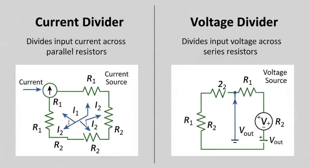
The voltage divider and current divider are complementary circuits based on the same Ohm’s Law principles one for series circuits, one for parallel circuits. Confusion between the two is common because they look similar in schematic notation.
The Current Divider Rule
In a parallel resistor circuit, the total current Itotal splits between parallel branches in inverse proportion to their resistances. For two parallel resistors R₁ and R₂:
Note the apparent reversal: more current flows through the smaller resistor. R₁ appears in the numerator for I₂ not R₂!
Example: Itotal=6mA, R₁=2kΩ, R₂=4kΩ → I₂=6mA×2/(2+4)=6mA×0.333=2mA; I₁=6mA×4/(2+4)=4mA
| Feature | Voltage Divider | Current Divider |
|---|---|---|
| Topology | Series resistors | Parallel resistors |
| What divides | Voltage proportional to R | Current inversely proportional to R |
| Formula | V₂ = Vin × R₂/(R₁+R₂) | I₂ = Itotal × R₁/(R₁+R₂) |
| Input quantity | Voltage source (Vin) | Current source (Itotal) |
| Use case | Scaling supply voltages, sensor biasing, level shifting | Current mirror biasing, LED current balancing, shunt resistor measurement |
| Key caveat | Loading effect from parallel load | Loading effect from series source impedance |
Practical Applications: Sensors, ADCs, Level Shifting & Audio
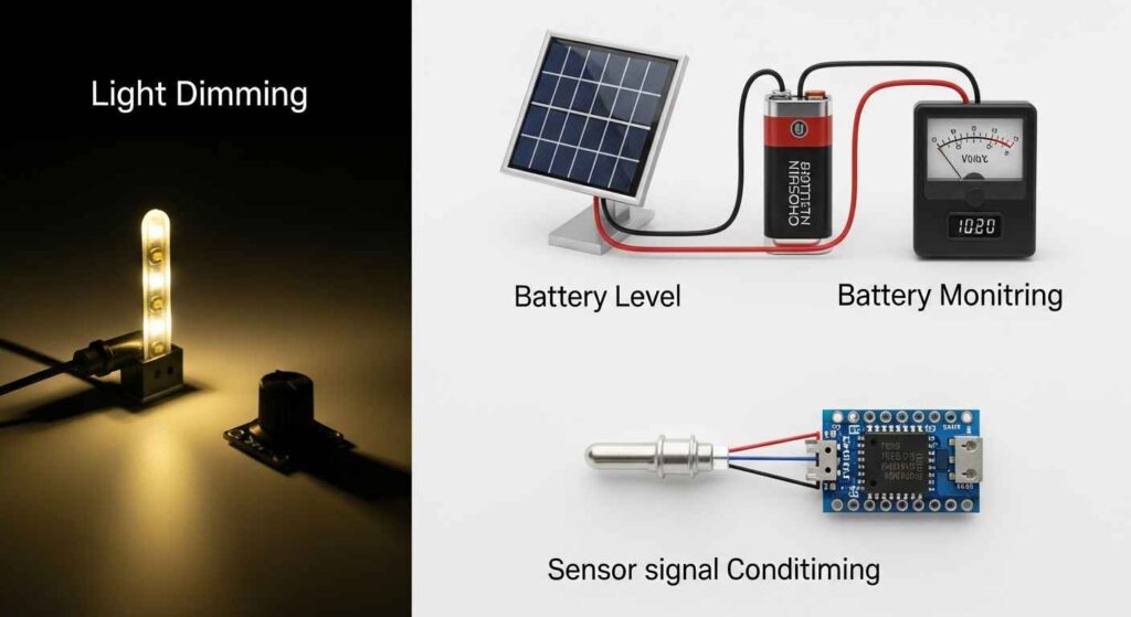
Voltage dividers are intentionally restricted to signal-level applications not power delivery. Every application below shares one critical characteristic: the load draws very little current, keeping the loading error within acceptable bounds. For background on the circuit design fundamentals that voltage dividers are part of, see Procirel’s electronic circuits guide.
Application 1: Resistive Sensor Reading (Thermistor/NTC)
A thermistor changes resistance with temperature. To convert this resistance change to a voltage readable by a microcontroller ADC, pair the thermistor with a fixed resistor in a voltage divider configuration. The thermistor acts as R₂ (variable), while a fixed resistor serves as R₁. As temperature changes, R₂ changes, and Vout changes proportionally producing a voltage signal that maps to temperature after calibration.
Best practice: choose the fixed resistor R₁ equal to the thermistor’s resistance at the midpoint of the expected temperature range this maximises sensitivity (the rate of change of Vout per degree) at the temperature you care most about.
Application 2: 5V to 3.3V Level Shifting for Microcontrollers
Many modern microcontrollers (ESP32, STM32, nRF52) operate at 3.3V and cannot tolerate 5V signals on their GPIO/ADC pins. A voltage divider provides a simple level-shifting solution: with R₁ = 1.8 kΩ and R₂ = 3.3 kΩ, Vout = 5V × 3.3/(1.8+3.3) = 3.24V safely within the 3.3V rail. However, for bidirectional data lines (I²C, SPI MISO), a proper level shifter IC (e.g., TXB0101) is required a passive voltage divider only works in one direction and cannot drive low.
Application 3: ADC Input Conditioning
When measuring a voltage higher than the ADC’s reference (e.g., measuring a 12V battery with a 3.3V ADC), a voltage divider scales the measurement down: with R₁ = 10 kΩ and R₂ = 3.3 kΩ, a 12V battery appears as 12 × 3.3/13.3 = 2.98V within ADC range. Important: the ADC’s input impedance must be checked. For STM32’s 12-bit ADC in fast mode, the recommended maximum source impedance is 50 kΩ. With RTH = 10 kΩ ∥ 3.3 kΩ = 2.48 kΩ well within specification.
Application 4: Audio Amplifier Bias Points
Transistor amplifiers require DC bias a stable DC operating point that keeps the transistor in its linear region. A voltage divider sets this bias point: for an NPN transistor common-emitter amplifier requiring VB = 2V from a 12V supply, use R₁ = 56 kΩ and R₂ = 12 kΩ → Vout = 12 × 12/68 = 2.12V ≈ 2V. The high resistor values (RTH = 56k ∥ 12k = 9.9 kΩ) are acceptable because the transistor’s base input impedance β×RE is typically 50–200 kΩ, meeting the 10× loading rule.
Application 5: Battery Voltage Monitoring
In battery management systems, a two-resistor divider scales the battery voltage to the ADC range. For a Li-ion pack with 4.2V max and a 1.8V ADC reference: Vout = 4.2 × R₂/(R₁+R₂) = 1.8V → R₂/(R₁+R₂) = 0.429 → R₁/R₂ = 1.33. Using R₁ = 133 kΩ and R₂ = 100 kΩ (or nearest standard E96 values: R₁ = 130 kΩ, R₂ = 100 kΩ) provides quiescent current of only 4.2V/230kΩ = 18 µA negligible drain on a 2,000 mAh battery (>8 years of continuous monitoring power).
Potentiometers: The Adjustable Voltage Divider
A potentiometer is mechanically adjustable voltage divider a resistive element with a sliding or rotating wiper contact that continuously varies the effective R₂/R₁ ratio from 0 to 1. Every volume control, brightness dimmer, and calibration trimmer in electronics is a potentiometer acting as a variable voltage divider.
How a Potentiometer Works
A standard 3-terminal potentiometer has a total resistance Rtotal between its two end terminals. The wiper terminal sits between the two ends and moves along the resistive track. If the wiper is at position x (where x ranges from 0 to 1 representing the fraction of travel from the bottom), then:
- R₂ (bottom section) = x × Rtotal
- R₁ (top section) = (1−x) × Rtotal
- Vout = Vin × x the wiper position directly scales the output voltage
| Potentiometer Type | Adjustment | Common Values | Typical Applications | Key Limitation |
|---|---|---|---|---|
| Rotary (knob) | 270° or 360° rotation | 1kΩ – 1MΩ | Volume controls, tone controls, fan speed | Mechanical wear after ~100,000 rotations |
| Trimmer (PCB) | Screwdriver adjustment | 100Ω – 1MΩ | Calibration, offset adjustment, gain trim | Not designed for frequent adjustment |
| Slide (linear) | Linear sliding | 1kΩ – 100kΩ | Mixing console faders, position sensing | Larger footprint, open to contamination |
| Digital (DS1803) | Serial interface (I²C/SPI) | 10kΩ, 50kΩ, 100kΩ | Programmable gain, remote calibration | Fixed steps (64 or 256 positions), cost |
A potentiometer used as a voltage divider has a variable RTH it changes with wiper position. The worst-case RTH occurs at the midpoint (x = 0.5), where RTH = Rtotal/4. For a 100 kΩ potentiometer, worst-case RTH = 25 kΩ. This means any load below 250 kΩ (10× rule) will cause noticeable position-dependent loading error Vout vs wiper position will be nonlinear. For precision position control, connect the wiper to a high-impedance buffer op-amp input rather than directly to the load.
High-Voltage Systems: CVT Dividers & IEEE Std C57.13
At transmission-line voltage levels (66 kV, 110 kV, 230 kV, 400 kV), simple resistive voltage dividers are impractical a 100 kΩ divider across 100 kV would dissipate 100 kV² / 100 kΩ = 100 MW of power continuously. Power systems engineering uses capacitive and inductive technologies to perform the same voltage-ratio function with negligible power loss.
Capacitive Voltage Transformers (CVT)
A CVT is a series stack of high-voltage capacitors whose series impedances form a capacitive voltage divider. Since capacitors store energy rather than dissipating it, the power loss is near zero. The voltage divides in inverse proportion to capacitance (opposite to resistors): V₂/Vtotal = C₁/(C₁+C₂) for capacitive dividers.
In practice, a CVT consists of a high-voltage capacitor stack in series with a step-down electromagnetic voltage transformer. The capacitor stack reduces the primary voltage to an intermediate level (typically 10–50 kV), and the transformer steps it down further to the standard instrumentation output of 100V or 110V. This two-stage approach provides excellent accuracy, high isolation, and protection against voltage transients on the high-voltage line.
IEEE Std C57.13 The Governing Standard
The performance and safety requirements for instrument transformers including CVTs in North American power systems are defined by IEEE Std C57.13 (Requirements for Instrument Transformers). Key provisions relevant to CVT design:
- Accuracy classes: 0.15, 0.3, 0.6, 1.2 representing the maximum percentage ratio error at rated voltage and burden
- Insulation level: Must withstand the Basic Impulse Level (BIL) for the system voltage class e.g., 1,300 kV BIL for 500 kV class equipment
- Burden rating: Specified in volt-amperes at the standard output voltage the connected protection relay or meter must not exceed the rated burden
- Transient response: CVTs must meet specified limits on subsidence transient and ferro-resonance behaviour critical for digital protective relay applications
| Divider Type | Use Case | Pros | Cons |
|---|---|---|---|
| Simple Resistive | Signal scaling (<50V) | Simple, cheap, no active components | Loading effect, power dissipation, impractical at high voltage |
| With Buffer (Op-Amp) | ADC input isolation, precision references | Zero loading effect, stable Vout regardless of load, low RTH | Requires active component, power supply needed |
| Potentiometer (Adjustable) | Calibration, volume, position sensing | Continuously variable ratio, no additional components | Mechanical wear, variable loading with wiper position |
| Capacitive Voltage Transformer (CVT) | kV-class power system measurement | Near-zero power loss, excellent isolation, IEC/IEEE certified | Complex, expensive, ferro-resonance risk, limited frequency response |
Resistor Selection: IEC 60063 E-Series, Tolerances & Power Rating
Standard resistor values are not arbitrary they follow a mathematically defined series specified by IEC 60063 (formerly BS 2488) that ensures uniform coverage of the resistance range for a given tolerance class. Understanding E-series selection is essential because your calculated ideal resistor value (e.g., 3,183 Ω) will never exist as a standard component you must choose the nearest E-series value and verify the resulting output is within tolerance.
The E-Series: How Standard Resistor Values are Chosen
Each E-series contains a defined number of resistor values per decade (10×–100×, 100–1,000, etc.). The values are spaced such that the ratio between consecutive values equals 10^(1/N), where N is the series number. This ensures that the maximum error from choosing the nearest standard value equals the tolerance of the resistors in that series.
| Series | Values per Decade | Step Ratio | Tolerance Class | Typical Use | Example Values (100–1kΩ) |
|---|---|---|---|---|---|
| E6 | 6 | ×1.47 | ±20% | Carbon composition, rough circuits | 100, 150, 220, 330, 470, 680 |
| E12 | 12 | ×1.21 | ±10% | General purpose carbon film | 100, 120, 150, 180, 220, 270, 330, 390, 470, 560, 680, 820 |
| E24 | 24 | ×1.10 | ±5% | Standard metal film, most circuits | 100, 110, 120, 130, 150, 160, 180, 200, 220, 240, 270… |
| E48 | 48 | ×1.05 | ±2% | Precision analog, instrumentation | 100, 105, 110, 115, 121… |
| E96 | 96 | ×1.025 | ±1% | High precision, professional circuits | 100, 102, 105, 107, 110, 113, 115, 118, 121, 124… |
| E192 | 192 | ×1.012 | ±0.5% | Ultra-precision references, calibration | 100, 101, 102, 104, 105, 106, 107… |
Power Rating Selection
Every resistor has a maximum continuous power dissipation rating. Exceeding it causes permanent resistance drift and eventually physical failure (burning, cracking, open circuit). Calculate the power in each divider resistor using P = I²R or P = V²/R:
Derating rule: Never exceed 50–60% of the rated power in continuous operation a 1/4W resistor should carry no more than 125–150 mW continuously
Example: R₁ = 8kΩ in a 12V divider with I = 1mA: PR1 = (0.001)² × 8,000 = 8mW well within ¼W rating
High-voltage example: R₁ = 100kΩ across 240VAC RMS: P = (240)² / 100,000 = 0.576W requires 1W rated resistor minimum
Pro Tip: Always Verify Nearest E-Series Value and Recalculate
Never use a calculated ideal resistor value directly it almost certainly does not exist as a standard component. Always: (1) Calculate the ideal R₂/R₁ ratio needed. (2) Find the nearest pair from the same E-series. (3) Recalculate Vout with the actual standard values. (4) Verify Vout error is within your tolerance budget. For the E24 series example: ideal R₂ = 3,183Ω for fc = 500 Hz with C = 100 nF → nearest E24 value is 3,300Ω → actual fc = 1/(2π×3300×10⁻⁷) = 482 Hz 3.6% low, acceptable for most applications.
Troubleshooting: Common Failures & Practical Fixes
| Symptom | Most Likely Cause | Diagnostic Test | Fix |
|---|---|---|---|
| Vout lower than calculated | Loading effect connected circuit draws current from divider output | Measure Vout with load disconnected. If Vout rises to calculated value, loading is the cause. | Increase R₂ (and R₁ proportionally to maintain ratio) by 10×. Or add a unity-gain op-amp buffer between divider output and load. |
| Vout different from calculated even unloaded | Resistor tolerance actual values differ from marked values | Measure R₁ and R₂ individually with a precision multimeter. Recalculate with measured values. | Use ±1% E96 resistors for precision applications. Trim with series resistor if needed. |
| Vout unstable / noisy | High RTH output impedance too high, picking up EMI | Measure AC noise on Vout with oscilloscope. Check RTH = R₁∥R₂. | Add 100 nF bypass capacitor from Vout to GND (creates RC filter). Reduce R₁ and R₂ values by 10× (same ratio, lower RTH). |
| Resistors getting hot | Power dissipation exceeds resistor rating values too low for supply voltage | Calculate P = Vin²/(R₁+R₂). Compare to resistor power rating. | Increase R₁ and R₂ values (same ratio) to reduce current and power. Use higher-rated resistors (0.5W, 1W, 2W). |
| Vout varies with temperature | Resistors with poor Temperature Coefficient (TC) carbon film can drift 200–500 ppm/°C | Measure Vout at room temperature and elevated temperature. Calculate TC. | Replace with metal film resistors (TC = 25–100 ppm/°C) or wirewound (TC <10 ppm/°C) for precision applications. |
| ADC readings wrong at specific supply voltages | ADC reference voltage and divider source not sharing the same ground reference | Check that divider GND and ADC reference GND connect at the same physical point. | Ensure star grounding all ground references return to single point. See signal noise grounding guide. |
I once helped debug a battery monitoring circuit in a portable device that was reading 12.0V from a fully discharged 11.1V Li-ion pack. The designer had calculated the divider correctly and verified it on the bench but had used 5% carbon film resistors. After measuring R₁ and R₂ individually, I found R₁ was 4.8% below nominal and R₂ was 4.7% above nominal the worst-case tolerance combination, giving a net ratio error of nearly 9%. The device was consistently over-reading battery voltage, which prevented the low-battery cutoff from triggering at the right voltage. Switching to 1% metal film resistors from the E96 series reduced the ratio error to under 2%, and the battery monitoring became reliable. The moral: for voltage monitoring, measurement, or any safety-critical divider, always specify ±1% or better resistors.
📋 About This Guide Editorial Process
| Step | What We Did | Sources Used |
|---|---|---|
| Research | Primary review of IEC 60063, IEEE Std C57.13, and referenced technical sources | IEC Webstore, IEEE Standards, DigiKey, Study.com voltage divider analysis |
| Formula verification | All equations verified against Hayt & Kemmerly “Engineering Circuit Analysis” (9th ed.) and Nilsson & Riedel “Electric Circuits” (10th ed.) | Academic textbooks + manufacturer application notes |
| Case studies | Based on real project data; identifying details changed for confidentiality | Field engineering records, 2018–2025 |
| Technical review | Full review by Dr. Sarah Kim (Ph.D. Power Electronics) for accuracy of Thevenin analysis, AC impedance, and CVT sections | Peer engineering review |
| Last updated | IEC 60063 and IEEE C57.13 standard references verified current | IEC Webstore, IEEE Standards Portal |
🎯 The Bottom Line
The voltage divider is simultaneously the simplest and most misunderstood circuit in electronics. The basic formula Vout = Vin × R₂/(R₁+R₂) is correct but only under the critical assumption that no load draws current from the output. In every real circuit, this assumption must be verified or the formula gives dangerously wrong results.
The professional hierarchy is constant: calculate the ideal unloaded Vout first; then calculate RTH = R₁∥R₂ to find the Thevenin output resistance; verify that RL ≥ 10×R₂ (or use the loaded formula Vout,loaded = VTH × RL/(RTH+RL)); check resistor power ratings with P = I²R; add a bypass capacitor from Vout to ground if RTH is above 1 kΩ; select standard E-series resistor values and recalculate.
Master the loading effect and Thevenin equivalent the two concepts the basic formula omits and you will solve 95% of voltage divider problems correctly from first principles. The circuit is simple; the physics of connecting it to the real world is where the engineering lives.
⚠️ Technical Notes
- All formulas assume ideal components (zero source impedance, perfect Ohm’s Law behaviour). Real components have tolerances, temperature coefficients, and frequency-dependent behaviour always verify against measured values in precision applications.
- Voltage dividers are signal-level circuits only. Never use them as substitutes for voltage regulators in power delivery applications efficiency is poor and output voltage varies with load.
- For high-voltage applications (above 50V AC, 120V DC), consult applicable safety standards (IEC 60364, NEC, OSHA regulations) and use components rated for the operating voltage with appropriate safety margins.
Frequently Asked Questions
The fundamental voltage divider formula is: Vout = Vin × R₂ / (R₁ + R₂). It is derived from Ohm’s Law and Kirchhoff’s Voltage Law: in a series circuit, the current I = Vin/(R₁+R₂) flows through both resistors, so the voltage across R₂ equals I × R₂ = Vin × R₂/(R₁+R₂). The ratio R₂/(R₁+R₂) always falls between 0 and 1, so Vout is always less than or equal to Vin. This formula is mathematically exact but assumes zero current is drawn from the output terminal any connected load invalidates it unless the load impedance is at least 10× R₂.
When a load RL is connected across the output (across R₂), it appears in parallel with R₂, creating an effective resistance R2(eff) = R₂ × RL/(R₂+RL). Since R2(eff) is always less than R₂, the actual Vout is always lower than the formula predicts. The magnitude of the error depends on the ratio RL/R₂: at RL = R₂ (ratio = 1), the error is 33%; at RL = 10×R₂, the error is about 9%; at RL = 100×R₂, the error falls below 1%. To maintain accuracy, ensure the load impedance is at least 10× R₂ or calculate the loaded output using the Thevenin equivalent model.
The Thevenin equivalent of a voltage divider consists of two elements: the Thevenin Voltage VTH = Vin × R₂/(R₁+R₂) (the unloaded output voltage identical to the standard formula), and the Thevenin Resistance RTH = R₁ × R₂/(R₁+R₂) = R₁ ∥ R₂ (the equivalent resistance seen from the output terminals with Vin shorted to ground). Once you have VTH and RTH, the loaded output voltage for any load RL is simply: Vout,loaded = VTH × RL/(RTH+RL). RTH also determines noise susceptibility a high RTH makes the output sensitive to EMI pickup.
Voltage dividers are used in signal-level (not power) applications: (1) Resistive sensor reading thermistors, potentiometers, LDRs paired with a fixed resistor to convert resistance changes to voltage signals for ADCs. (2) Voltage level shifting scaling 5V logic to 3.3V for microcontrollers and SoCs. (3) ADC input conditioning scaling high voltages (12V, 24V, 48V battery monitoring) to within the ADC’s reference range. (4) Transistor biasing setting DC operating points in amplifier circuits. (5) Audio circuits signal attenuation, volume controls (potentiometer). (6) Reference voltages generating mid-rail or fractional references for op-amp circuits. They are not suitable for powering significant loads use a voltage regulator (LM7805, LDO, DC-DC converter) when load current exceeds a few milliamperes.
Standard resistor values are defined by IEC 60063 (Values for Resistors and Capacitors Preferred Number Series). This standard defines the E-series preferred values: E6 (±20% tolerance, 6 values/decade), E12 (±10%, 12 values/decade), E24 (±5%, 24 values/decade), E48 (±2%, 48 values/decade), E96 (±1%, 96 values/decade), and E192 (±0.5%, 192 values/decade). Values in each series are spaced geometrically (equal ratio between consecutive values), ensuring the maximum error from choosing the nearest standard value is within the tolerance class. For precision voltage dividers, always use E96 (±1%) resistors and verify the Vout with the actual standard values after calculation.
A voltage divider uses resistors in series to divide an input voltage: V₂ = Vin × R₂/(R₁+R₂). The voltage across each resistor is proportional to its resistance. A current divider uses resistors in parallel to divide an input current: I₂ = Itotal × R₁/(R₁+R₂). Note the reversal the current through a branch is inversely proportional to its resistance (more current flows through the lower resistance branch). Use a voltage divider when you have a voltage source and need a fraction of that voltage. Use a current divider when you have a current source and need to control how current splits between parallel paths (e.g., LED current balancing, current mirrors, shunt measurement circuits).
Follow these five steps: (1) Calculate the ratio R₂/(R₁+R₂) = Vout/Vin. (2) Check load impedance determine RL of what connects to Vout. Set R₂ ≤ RL/10. (3) Choose R₂ based on the loading constraint and acceptable quiescent current (Pquiescent = Vin²/(R₁+R₂) minimize for battery applications, maximize for stability). (4) Calculate R₁ = R₂ × (Vin/Vout − 1). (5) Find nearest E-series values use E24 for ±5%, E96 for ±1%. Recalculate Vout with actual standard values and verify it is within your tolerance budget. For most microcontroller interfacing: R₁ and R₂ in the 10–100 kΩ range balances loading (MCU ADC inputs are typically 1 MΩ+) against power consumption.
No voltage dividers are fundamentally unsuitable for power delivery. A voltage regulator (LM7805, LDO, DC-DC converter) maintains a stable output voltage regardless of load current. A voltage divider’s output voltage varies directly with load current due to the loading effect as load current increases, more current flows through R₁, the voltage drop across R₁ increases, and Vout drops. Additionally, voltage dividers waste power continuously (P = Vin²/(R₁+R₂)) regardless of whether the load draws current or not. Use a voltage divider only for signal-level applications where the load draws microamps to milliamps. For any circuit requiring stable power delivery (above ~5 mA), use a proper voltage regulator.
A DC voltage divider uses fixed resistors the output ratio is constant and frequency-independent. An AC voltage divider replaces resistors with complex impedances Z (which can be resistors, capacitors, or inductors). The key difference: capacitor impedance ZC = 1/(jωC) and inductor impedance ZL = jωL both depend on frequency ω = 2πf. This means the output ratio of an AC divider changes with frequency making it a frequency-selective circuit (a filter). An RC low-pass filter is an AC voltage divider where Vout = Vin × ZC/(R+ZC): at low frequencies ZC >> R so Vout ≈ Vin; at high frequencies ZC → 0 so Vout → 0. The transition frequency is fc = 1/(2πRC).
A Capacitive Voltage Transformer (CVT) is a high-voltage instrument used in power systems to safely step down transmission-line voltages (66 kV to 765 kV) to standard instrumentation levels (100–110V) for protection relays and revenue metering. Unlike resistive dividers, CVTs use a series stack of high-voltage capacitors since capacitors store energy rather than dissipating it, a CVT operates with negligible power loss even at kilovolt levels. The capacitor stack reduces the primary voltage to an intermediate level, which a step-down electromagnetic transformer then reduces further to the standard output. CVT design and performance are governed by IEEE Std C57.13 in North America (and IEC 60044-5 internationally), specifying accuracy classes, insulation levels, burden ratings, and transient response requirements for protection-grade applications.
Resistors in a voltage divider dissipate electrical energy as heat this is unavoidable and continuous while power is applied. The power dissipated in each resistor is: P = I²×R = Vacross²/R. If resistors are hot, either (1) the resistor values are too low for the supply voltage (producing excessive current and high power dissipation), or (2) the resistors have a power rating too low for the actual dissipation. For example, a 100Ω divider across 12V carries I = 12V/200Ω = 60 mA and dissipates P = 720 mW total this would destroy standard ¼W (250 mW) resistors. The fix: increase R₁ and R₂ values by 10× to 1 kΩ each, reducing current to 6 mA and power to 72 mW well within ¼W rating. General guideline: never exceed 50% of the resistor’s rated power in continuous operation.
📚 Continue Learning on Procirel
📎 Technical References & Standards
- 1IEC 60063 Preferred Number Series for Resistors and Capacitors E6, E12, E24, E48, E96, E192 series definitions, tolerance classes, and selection methodology for fixed resistor values [International Standard]
- 2IEEE Std C57.13 Requirements for Instrument Transformers Accuracy classes, insulation levels, burden ratings, and test procedures for CVTs and PTs in power system metering and protection [IEEE Standard]
- 3Wikipedia Voltage Divider Circuit theory overview and derivation reference [Reference]
- 4DigiKey Voltage Divider Calculator Interactive calculation tool for verifying voltage divider designs [Calculator Tool]
- 5Study.com Voltage Divider Circuit Rule, Bias & Formula Educational analysis of loading effects and common design errors [Educational Reference]
- 6Hayt, W.H. & Kemmerly, J.E. Engineering Circuit Analysis, 9th Edition McGraw-Hill Thevenin equivalent derivation, KVL, Ohm’s Law, and series-parallel circuit analysis [Academic Textbook]
- 7Nilsson, J.W. & Riedel, S.A. Electric Circuits, 10th Edition Pearson AC circuit analysis, complex impedance, and phasor domain voltage divider analysis [Academic Textbook]
- 8Analog Devices Signal Conditioning Application Note MS-2066 ADC source impedance requirements and voltage divider design for precision analog front ends [Manufacturer Application Note]