DPDT Switch: Complete Wiring Guide, H-Bridge Motor Control & Standards
The definitive professional guide from 6-pin pinout and internal logic to H-bridge motor reversal, contact resistance formulas, ON-ON vs ON-OFF-ON configurations, and UL/IEC compliance.
Key Takeaways
- ✅ A DPDT switch has 6 pins: Pins 2 & 5 are Commons (input), Pins 1 & 4 are Throw 1 (NC), Pins 3 & 6 are Throw 2 (NO)
- ✅ It is functionally two SPDT switches in one body, both operated by a single lever simultaneously
- ✅ The killer application: H-bridge DC motor reversal cross-wiring Pins 1→6 and 3→4 flips motor polarity without any microcontroller
- ✅ Contact resistance (Rc) causes power loss Ploss = I²·Rc a healthy switch reads below 100 mΩ; above 500 mΩ indicates failure
- ✅ Three main configurations: ON-ON (always connected), ON-OFF-ON (center neutral), and Momentary (spring-return)
- ✅ Always derate to 1.5× the motor’s stall current; use DC-rated contacts for motor loads to prevent contact arcing
- ✅ Compliance standards: UL 1054, IEC 60947-5-1, IEC 60669 mandatory for commercial and industrial designs
What Every Engineer Must Know About DPDT Switches
A DPDT is electrically identical to two SPDT switches mechanically ganged on a single actuator. Both poles switch simultaneously with one flip that’s the entire design secret.
DC motor loads are far more destructive to contacts than AC. DC arcs do not self-extinguish at zero-crossing always select a switch with explicit DC voltage/current ratings, not just AC ratings.
A switch rated for 500,000 mechanical cycles may only survive 10,000–100,000 electrical cycles under rated load. The arc from switching inductive loads burns contact surfaces at every cycle.
Motor reversal requires diagonal cross-connections: Pin 1→Pin 6 and Pin 3→Pin 4. A missing cross-wire produces a short circuit in one position the most common wiring mistake in the field.
Mechanical contacts don’t close cleanly they bounce 1–10 ms, creating multiple rapid open/close events. For digital circuits, software debouncing or a 10 nF capacitor across the output is essential.
Every inductive load (motor, relay, solenoid) generates a back-EMF spike at switch-off. Without a flyback diode across the load, this voltage spike kills switch contacts within hundreds of cycles.
What is a DPDT Switch and How Does It Work?
A DPDT (Double Pole Double Throw) switch is a 6-terminal electromechanical device that functions as two independent SPDT switches mechanically coupled to a single actuator. When the lever is flipped, both poles switch simultaneously connecting each Common terminal to one of its two Throw terminals. This dual-channel architecture enables a single mechanical action to simultaneously reroute two separate circuits, making it the standard component for DC motor polarity reversal, stereo audio A/B switching, and dual-supply selection.
The switch contains two movable conductive bridges (poles), each of which can connect a center Common pin to one of two fixed contacts (throws). In Position A, each COM connects to Throw 1 (pins 1 & 4). In Position B, each COM connects to Throw 2 (pins 3 & 6). The result: complete, simultaneous control of two independent circuits with a single actuator movement.
Table of Contents
- 6-Pin Terminal Configuration & Internal Logic
- How a DPDT Switch Works: The Physics of Pole Switching
- ON-ON, ON-OFF-ON & Momentary Configurations Compared
- H-Bridge Motor Reversal: Step-by-Step Wiring & Physics
- Contact Resistance, Power Loss & Cycle Life Formulas
- DPDT Switch Types: Toggle, Rocker, Slide, Relay Compared
- Professional Wiring Guide: Motor, Audio & Power Circuits
- DPDT vs SPDT vs DPST: Quantitative Comparison
- Engineering Selection: Voltage, Current & Environment
- UL/IEC Standards, Diagnostics & Contact Wear Analysis
- Case Studies: Motor Control, Audio & Industrial Automation
- Troubleshooting: Failure Modes, Diagnostics & Fixes
- Frequently Asked Questions
6-Pin Terminal Configuration & Internal Logic

The DPDT switch’s 6-pin architecture is the foundation of every wiring decision. Misunderstanding the pin mapping is the single most common cause of reverse-wiring faults in motor control circuits. Every DPDT switch regardless of whether it is a toggle, rocker, slide, or relay follows the same fundamental internal structure.
Standard 6-Pin Terminal Assignment
| Pin Number | Terminal Name | Function | Position A Connection | Position B Connection |
|---|---|---|---|---|
| Pin 2 | Common 1 (COM1) | Power input for Pole 1 | → Pin 1 (Throw 1) | → Pin 3 (Throw 2) |
| Pin 5 | Common 2 (COM2) | Power input for Pole 2 | → Pin 4 (Throw 1) | → Pin 6 (Throw 2) |
| Pin 1 | NC / Throw 1A | Output: Switch UP position | Connected to COM1 | Disconnected |
| Pin 4 | NC / Throw 1B | Output: Switch UP position | Connected to COM2 | Disconnected |
| Pin 3 | NO / Throw 2A | Output: Switch DOWN position | Disconnected | Connected to COM1 |
| Pin 6 | NO / Throw 2B | Output: Switch DOWN position | Disconnected | Connected to COM2 |
NC (Normally Closed) means the pin is connected to COM in the switch’s default/resting position these are Pins 1 and 4 when the switch is in the UP state. NO (Normally Open) means the pin is only connected when the switch is actively thrown to the opposite position Pins 3 and 6. In a toggle switch, “normally closed” refers to the position the internal spring returns to if there is no sustained force. This distinction is critical when wiring fail-safe circuits where the default state must be known.
How a DPDT Switch Works: The Physics of Pole Switching
Inside every DPDT switch body are two independent electrical circuits the two “poles” each containing a spring-loaded movable conductive bridge. This bridge is attached to the actuator lever through a mechanical linkage. When you flip the lever, both bridges move simultaneously and identically, making or breaking connections at both poles at the exact same moment.
The Switching Sequence
Rest Position (Position A UP)
The internal spring holds both movable bridges against Throw 1 contacts (Pins 1 and 4). COM1 (Pin 2) is connected to Pin 1. COM2 (Pin 5) is connected to Pin 4. The NO contacts (Pins 3 and 6) are open-circuit no current path exists through them.
Transition (The Critical Arc Zone)
As the lever travels between positions, both bridges momentarily leave their previous contacts before touching the new ones a condition called the open transition. During this brief period (typically 1–5 milliseconds), both circuits are open simultaneously. The moving contact also bounces 3–8 times on contact, creating brief repeated open/close events critical to handle in digital signal applications.
Active Position (Position B DOWN)
Both bridges now rest against Throw 2 contacts. COM1 (Pin 2) connects to Pin 3. COM2 (Pin 5) connects to Pin 6. The NC contacts (Pins 1 and 4) are now open. The simultaneous switching of both poles is guaranteed by the rigid mechanical coupling there is no possibility of one pole switching before the other in a properly functioning switch.
Contact Bounce and Why It Matters
When the movable bridge hits a fixed contact, the metal-to-metal impact causes microscopic elastic vibration the conductive bridge literally bounces 1–10 times in the first 1–10 milliseconds before settling into stable contact. For a motor or lamp circuit, this bounce is imperceptible. For a microcontroller input counting edges, 8 bounces registers as 8 switch presses. The solutions are straightforward:
- Hardware debounce: A 10–100 nF capacitor between the switch output and ground, combined with a 10 kΩ pull-up resistor, creates an RC filter with time constant τ = RC that smooths the bounce transitions
- Software debounce: In Arduino or other MCU code, ignore state changes for 20–50 ms after the first detected edge
- Schmitt trigger IC: A 74HC14 hex Schmitt trigger inverter provides hysteresis that cleanly converts a bouncy switch signal to a sharp digital edge
I once spent an entire afternoon debugging a microcontroller-based motor sequencer that appeared to randomly trigger multiple direction changes from a single DPDT switch press. The logic analyzer revealed 6–9 bounces on every switch actuation, each bounce being interpreted as a valid edge. Adding a 47 nF capacitor and 10 kΩ resistor as an RC filter eliminated the problem completely. Total fix cost: approximately $0.05 in components. Total debugging time lost: 4 hours. The lesson: never connect a mechanical switch directly to a digital input without hardware debouncing it will misbehave in the field even if bench testing looks clean.

ON-ON, ON-OFF-ON & Momentary Configurations Compared
The same 6-pin DPDT body is available in three fundamentally different contact action configurations. Selecting the wrong configuration is a common design error that only manifests during testing and sometimes not until field deployment.
| Configuration | Positions | Center State | Spring Return | Primary Use Cases |
|---|---|---|---|---|
| ON-ON Most Common | 2 | None always active | No | Motor direction, A/B source switching, polarity reversal |
| ON-OFF-ON | 3 | Full disconnect (OFF) | No | Motor stop/forward/reverse, 3-speed fan, selector circuits |
| Momentary ON-ON | 2 (spring-return) | Returns to Position A | Yes | Jog control, test pulse, momentary relay activation |
| Momentary ON-OFF-ON | 3 (spring-center) | Spring returns to OFF | Yes | Up/down motor jog, servo positioning |
A toggle switch body that looks identical externally may be ON-ON or ON-OFF-ON depending on the internal spring assembly. These two configurations behave completely differently: an ON-ON in a motor control circuit where you needed ON-OFF-ON means the motor can never be fully stopped without disconnecting power. Always check the datasheet part number suffix most manufacturers use suffixes like “-73” for ON-ON and “-75” for ON-OFF-ON.
H-Bridge Motor Reversal: Step-by-Step Wiring & Physics

The most powerful and widely used application of the DPDT switch is the manual H-bridge a wiring configuration that reverses the polarity of a DC motor without any electronic controller. This is how RC vehicles back up, how motorised blinds reverse direction, and how garage door openers return to position all with a single mechanical switch flip.
Step-by-Step H-Bridge Wiring
Connect the Power Supply to the Common Pins
Attach the battery or power supply positive (+V) terminal to Pin 2 (COM1). Attach the negative (GND) terminal to Pin 5 (COM2). These center pins are your power inputs. Add an inline fuse rated at 1.5× the motor’s stall current between the battery positive and Pin 2.
Install the Critical Cross-Wire Connections
Using a short jumper wire, connect Pin 1 to Pin 6 (diagonal cross-connection). Using a second jumper wire, connect Pin 3 to Pin 4 (diagonal cross-connection). These two cross-wires are the polarity-reversal mechanism. Without them, you get forward-only operation and potentially a short circuit in Position B.
Connect the Motor to Pins 1 and 3
Attach one motor terminal to Pin 1 and the other motor terminal to Pin 3. Do not connect the motor to Pins 4 or 6 those are the cross-wired return paths, not the motor output terminals in this configuration.
Install a Flyback Diode Across the Motor
Place a 1N4007 diode (or equivalent fast-recovery diode for high-speed motors) across the motor terminals cathode at the motor’s positive side, anode at the negative side. This diode absorbs the back-EMF voltage spike generated when the motor is switched off or reversed, protecting switch contacts from arc damage.
The Physics: Why Cross-Wiring Reverses Polarity
In Position A: COM1 (Pin 2, +V) connects to Pin 1 → Motor terminal A receives positive voltage. COM2 (Pin 5, GND) connects to Pin 4 → through the cross-wire (Pin 4 to Pin 3) → Motor terminal B receives ground. Current flows A→B through the motor, producing rotation in Direction 1.
In Position B: COM1 (Pin 2, +V) connects to Pin 3 → through the cross-wire (Pin 3 to Pin 4) → Motor terminal B now receives positive voltage. COM2 (Pin 5, GND) connects to Pin 6 → through the cross-wire (Pin 6 to Pin 1) → Motor terminal A now receives ground. Current flows B→A reversed producing rotation in Direction 2.
Key insight: Reversing v⃗ (current direction) reverses F⃗ (force direction) → motor spins opposite way
Position A: Current +V→Pin2→Pin1→Motor(A+) | Position B: Current +V→Pin2→Pin3→Motor(B+) polarity flipped
If you omit the cross-wire connections (Pin 1↔Pin 6 and Pin 3↔Pin 4) and connect power directly, Position B will short your positive and negative supply rails together through the switch contacts. The only thing between your battery and a dead short will be the switch’s contact resistance typically a few milliohms. Stall currents of 10–50A are possible in seconds, sufficient to weld contacts, melt wiring, or cause a fire. Always double-check cross-wire installation before applying power.
Contact Resistance, Power Loss & Cycle Life Formulas
Professional switch selection and fault diagnosis require quantitative understanding of four key metrics: contact resistance, conduction loss, electrical life, and thermal limits. These parameters determine whether a switch will survive its intended service life or fail prematurely.
Silver alloy: ρ ≈ 1.6 × 10⁻⁸ Ω·m (low loss) | Gold plating: ρ ≈ 2.4 × 10⁻⁸ Ω·m (best for low-current signals)
Design target: Rc < 100 mΩ on new switch | Replace when Rc > 500 mΩ
Example: I = 5A, Rc = 50 mΩ → Ploss = 25 × 0.05 = 1.25W acceptable in a standard toggle
Warning: I = 5A, Rc = 500 mΩ (worn contacts) → Ploss = 25 × 0.5 = 12.5W overheating, imminent failure
For reliable debouncing: τ should be 5–20 ms (longer than worst-case bounce duration)
Example: R = 10 kΩ, C = 100 nF → τ = 10,000 × 0.0000001 = 1 ms borderline; use C = 1 µF for τ = 10 ms
Motor stall current is typically 4–10× the running current. Never use running current alone for switch selection.
Example: Motor runs at 2A, stalls at 8A → Switch must be rated ≥ 1.5 × 8A = 12A minimum
Electrical vs Mechanical Life: The Critical Distinction
| Life Metric | Definition | Typical Value | Limiting Factor | Design Implication |
|---|---|---|---|---|
| Mechanical Life | Total actuations before lever/spring failure | 50,000–500,000 cycles | Metal fatigue in spring/cam | Relevant for high-frequency operation |
| Electrical Life (Full Load) | Actuations under rated load before contact failure | 10,000–100,000 cycles | Contact erosion from switching arc | Always design around this not mechanical life |
| Electrical Life (DC Motor) | Actuations with inductive motor load | 5,000–30,000 cycles | Back-EMF arc burns contact surface | Add flyback diode to extend life 5–10× |
Pro Tip: Extend Electrical Life with Snubber Circuits
For DC motor applications, a simple RC snubber (typically 100 Ω + 100 nF in series) placed across the motor terminals significantly reduces the arc energy at every switch transition. The capacitor absorbs the initial voltage spike and the resistor damps the oscillation. Combined with a flyback diode, this can extend electrical contact life by 3–8× compared to an unprotected motor circuit a critical measure when the switch will see hundreds of direction reversals per day.
DPDT Switch Types: Toggle, Rocker, Slide & Relay Compared
The DPDT function is available in five distinct physical form factors, each optimized for different environments, current ratings, and mounting requirements. The internal 6-pin logic is identical across all types only the actuation mechanism and enclosure differ.
DPDT Toggle Switch
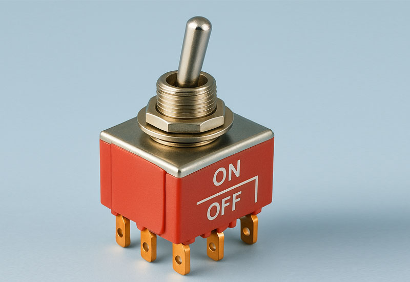
The most widely deployed DPDT form factor in industrial and DIY electronics. A threaded metal bushing mounts through a panel hole, secured with a nut. Available in standard, subminiature, and miniature sizes. Toggle switches offer the clearest visual state indication lever position is immediately visible from across a room making them the standard choice for control panels and laboratory equipment.
A quality DPDT toggle switch from manufacturers like Carling Technologies or E-Switch withstands 10,000 to 100,000 electrical cycles under full rated load, and 500,000+ mechanical cycles. Waterproof boot versions (IP67) are available for harsh environments. For in-depth treatment of how these switches are used in household wiring contexts, Procirel’s guide on two-way switch wiring covers similar switching principles applied to domestic electrical systems.
DPDT Rocker Switch
The dominant form factor in consumer appliances the “seesaw” actuator provides a larger contact surface for easier operation and a more modern aesthetic. Rocker switches snap into rectangular panel cutouts without tools, making installation significantly faster than toggle switches. They are available in illuminated versions with integrated LED indicators showing switch state.
For automotive applications, illuminated rocker switches rated for 12V DC (e.g., Nilight or Blue Sea Systems series) provide waterproof (IP65) operation with 20A DC ratings sufficient for most automotive accessory loads including compressors, winches, and lighting bars.
DPDT Slide Switch
The slide switch moves a conductive bridge laterally rather than rotating it. The compact form factor makes it ideal for PCB-mount applications and portable devices. The trade-off is lower current ratings typically 0.5A to 3A maximum and sensitivity to contamination from dust or flux residue in the sliding channel. Use slide switches exclusively for signal-level switching (logic, audio signals, sensor selection) and avoid them for any power-carrying circuit above a few amperes.
DPDT Relay Switch
The DPDT relay replaces the mechanical lever with an electromagnetic coil. When coil current flows (typically 10–100 mA at 5V, 12V, or 24V control voltage), the magnetic field pulls the armature, switching both poles simultaneously. Relays provide complete galvanic isolation between the control circuit and the switched load the control signal never touches the switched power making them essential for MCU-controlled high-power applications.
The DPDT relay’s key advantage is the ability to switch high-current DC loads (10A, 20A, 30A) using a 3.3V or 5V logic signal through a transistor driver stage. The key limitation is switching speed mechanical relays take 5–20 ms to close, making them unsuitable for PWM or high-frequency applications. For those, a MOSFET H-bridge is appropriate; for background on MOSFET switching fundamentals, see Procirel’s guide on MOSFET as a switch.
| Type | Typical I Rating | Mounting | Actuation | IP Rating | Best Use Case |
|---|---|---|---|---|---|
| Toggle | 5A–20A AC/DC | Panel (threaded) | Manual lever | IP00–IP67 | Control panels, lab instruments, industrial machinery |
| Rocker | 10A–20A AC/DC | Panel (snap-in) | Seesaw button | IP40–IP65 | Consumer appliances, automotive, marine electronics |
| Slide | 0.4A–3A | PCB or panel | Linear slider | IP00–IP40 | Signal routing, portable devices, PCB signal selection |
| Relay (Electromechanical) | 10A–30A | PCB, socket, DIN rail | Electromagnetic coil | IP20–IP54 | MCU-controlled loads, safety interlocks, automation panels |
| Reed Relay | 0.25A–1A | PCB | Magnetic field (coil) | N/A (sealed) | Low-current signal switching, instrumentation, medical |
Professional Wiring Guide: Motor, Audio & Power Circuits
Application 1: DC Motor Direction Control (H-Bridge)
Covered in depth in Section 4. Key wiring summary: Battery(+) → Pin 2, Battery(−) → Pin 5, cross-wire Pin 1↔Pin 6 and Pin 3↔Pin 4, motor between Pins 1 and 3. Add flyback diode across motor terminals. Use 14–16 AWG wire for motors drawing up to 15A; use 10–12 AWG for motors rated above 15A.
Application 2: Stereo Audio A/B Source Switching
In stereo audio systems, the DPDT switch’s dual-pole nature perfectly matches the Left/Right channel architecture. Both audio channels switch simultaneously with a single flip, ensuring phase-coherent switching with no L/R timing skew. The wiring principle is identical to motor reversal but with signal-level voltages:
- Pole 1 (Pins 1, 2, 3): Routes the LEFT channel Source A Left → Pin 1, Source B Left → Pin 3, Output Left → Pin 2 (COM)
- Pole 2 (Pins 4, 5, 6): Routes the RIGHT channel Source A Right → Pin 4, Source B Right → Pin 6, Output Right → Pin 5 (COM)
Use a gold-contact, low-noise DPDT switch (E-Switch 100DP or equivalent) for audio applications. Standard power switches have contact resistance variations that are inaudible at power levels but can introduce measurable noise at microphone-level signal voltages below 100 mV.
Application 3: Dual-Source Power Selection
A DPDT switch can safely select between two isolated power sources (e.g., mains adapter vs. battery backup). Pole 1 switches the positive rail; Pole 2 simultaneously switches the return/ground. This two-pole switching ensures complete source isolation a single-pole switch leaving a shared return/ground can create ground loops and potentially dangerous ground potential differences between sources. This circuit is the basis of manual transfer switches used in UPS systems and generator transfer panels, subject to IEC 60947-3 for the switching apparatus.
Wire Gauge Selection Guide
| Current (A) | Wire Gauge (AWG) | Wire Gauge (mm²) | Application Example |
|---|---|---|---|
| Up to 1A | 22–24 AWG | 0.34–0.5 mm² | Signal switching, LED indicators |
| 1A–5A | 18–20 AWG | 0.75–1.0 mm² | Small DC motors, 12V accessories |
| 5A–15A | 14–16 AWG | 1.5–2.5 mm² | Automotive motors, power tools, lighting |
| 15A–25A | 10–12 AWG | 4–6 mm² | Heavy motors, winches, compressors |
| Above 25A | 8 AWG or larger | 10 mm² or larger | Industrial loads consult NEC/IEC 60364 |
1. Strain relief first: A dab of hot glue or a cable tie within 25 mm of each terminal prevents vibration from fatiguing the wire at the solder point the most common field failure in mobile applications. 2. Stranded over solid: Stranded wire tolerates repeated flexing; solid wire work-hardens and breaks at bends after 50–200 flex cycles. Use stranded exclusively for panel-mounted switches. 3. Torque your terminals: Screw terminals on DPDT switches should be torqued to the manufacturer’s specification (typically 0.5–0.8 N·m for M3 terminals). Under-torqued connections increase contact resistance by 10–100× within months of service.
DPDT vs SPDT vs DPST: Quantitative Comparison
Switch type confusion causes more design rework than almost any other component selection error. The three most commonly confused types SPDT, DPST, and DPDT look similar externally but have fundamentally different internal architectures and capabilities.
| Feature | SPDT | DPST | DPDT |
|---|---|---|---|
| Full Name | Single Pole Double Throw | Double Pole Single Throw | Double Pole Double Throw |
| Terminal Count | 3 | 4 | 6 |
| Independent Circuits Controlled | 1 | 2 | 2 |
| Output Positions | 2 (A or B) | 1 (ON or OFF only) | 2 (A or B, both circuits) |
| Motor Reversal Possible? | No single pole only | No no throw options | Yes ✓ |
| Stereo Audio Switching? | No only one channel | No only ON/OFF | Yes ✓ |
| Best Use Case | Single-channel routing, 3-way lamp circuits | Two-circuit ON/OFF (e.g., dual heating elements) | Motor reversal, A/B switching, polarity reversal |
✅ DPDT Advantages Over Alternatives
- Controls two completely independent circuits simultaneously stereo audio, dual-phase power
- Enables polarity reversal (H-bridge) with zero additional components
- Single actuator ensures perfectly synchronous switching of both poles no timing skew possible
- More economical than installing two separate SPDT switches and a mechanical linkage
- Available in same package sizes as SPDT direct drop-in upgrade for added functionality
- Provides complete load isolation in dual-source switching (both poles switch positive AND return)
⚠️ DPDT Limitations
- More complex wiring 6 terminals increase the probability of wiring errors vs. simpler types
- Higher cost than SPDT or DPST for equivalent current ratings
- Larger body size not always available in ultra-miniature PCB form factors
- Both poles always switch together cannot independently control each pole (requires two separate switches)
- DC motor loads drastically reduce electrical life requires protection components
- Not suitable for high-frequency switching (relay/toggle versions limited to a few Hz at most)
Engineering Selection: Voltage, Current & Environment
Selecting the wrong DPDT switch is one of the most common root causes of premature field failure in DIY and professional electronics alike. The correct approach requires evaluating ten interdependent parameters not just the headline voltage and current ratings.
| Selection Factor | Parameter to Check | Rule of Thumb |
|---|---|---|
| Voltage Rating (AC) | Maximum AC voltage (VAC) | Rating ≥ 1.25× circuit voltage. Standard: 125VAC or 250VAC |
| Voltage Rating (DC) | Maximum DC voltage (VDC) | DC rating is usually 30–50% of AC rating for same switch. Verify separately. |
| Current Rating | Continuous current at rated voltage | ≥ 1.5× motor stall current; use rated not running current |
| Contact Material | Silver alloy, gold, copper | Silver for power loads; gold for signal-level (<100 mA) switching |
| Configuration | ON-ON, ON-OFF-ON, Momentary | Verify the exact part number suffix visual appearance alone is unreliable |
| Actuator Type | Toggle, rocker, slide, pushbutton | Toggle for control panels; rocker for appliances; slide for PCB signal switching |
| Terminal Type | Solder lug, screw, QC, PCB pin | Screw for power circuits; solder lug for chassis wiring; PCB pins for populated boards |
| Environmental Protection | IP rating (IEC 60529) | IP65 minimum for splash exposure; IP67 for immersion; IP40 for dry indoor use |
| Certifications | UL, CE, CSA, RoHS | UL 1054 for North America; IEC 60947-5-1 for international industrial; CE for EU sale |
| Electrical Life | Cycles at rated load | Industrial: ≥ 100,000 cycles minimum; consumer: ≥ 10,000 cycles |
Tested DPDT Switch Recommendations by Application
High-Current Industrial Control (20A, 125VAC): Carling Technologies 2GM51-73 screw terminals, ON-ON, rated for 100,000 cycles. Battle-tested in industrial motor control panels. Panel-mount with threaded bushing, suitable for NEMA 4 enclosures with appropriate boot.
Audio Signal Switching (6A, 125VAC): E-Switch 100DP3T1B1M1QEH solder lugs, ON-OFF-ON, silver contacts with gold flash. The center-off position allows silent source changes. Recommended for A/B speaker comparators and studio patch bays.
Automotive / Marine (20A, 12VDC): Nilight Rocker Switch Series waterproof IP65, illuminated, snap-in mounting. Verified for off-road vehicles, marine control panels, and RV accessory circuits. Snap-in fit eliminates drilling/threading for common DIN panel cutouts.
PCB Signal Routing (0.4VA max): C&K 7211J2ZQE2 right-angle PCB mount, miniature, gold contacts. Ideal for instrument-level signal selection and battery polarity on compact circuit boards.
UL/IEC Standards, Diagnostics & Contact Wear Analysis
Professional and commercial switch selection requires verified compliance with industry standards. These standards exist because undersized or non-compliant switches are a documented cause of electrical fires and equipment failures not a theoretical concern.
Mandatory Compliance Standards
- UL 1054 (Underwriters Laboratories): Standard for General-Use Switches. Required for product sale in North America. Tests include endurance (10,000 operations at rated load), temperature rise, dielectric withstand, and overload switching. A UL-listed switch guarantees minimum performance to a verified, independently tested level.
- IEC 60947-5-1 (International Electrotechnical Commission): Governing low-voltage switchgear and controlgear the primary international standard for industrial DPDT applications. Specifies contact ratings, mechanical and electrical endurance, clearance and creepage distances, and EMC requirements. Mandatory for CE-marked products sold in the EU.
- IEC 60669 (Switches for Household Fixed Electrical Installations): The primary standard for rocker and toggle switches in domestic wiring applications. Specifies heat resistance, mechanical endurance (40,000 cycles minimum for household grade), and insulation requirements.
- NEMA Enclosure Ratings (e.g., NEMA 4, 4X, 6P): Define environmental protection levels NEMA 4 provides protection against splashing water, dust, and ice; NEMA 6P adds protection against temporary submersion. Relevant for the switch body/enclosure rather than the internal electrical contacts.
Professional Diagnostic Procedure: Contact Wear Analysis
An intermittent DPDT switch in the field should be diagnosed not simply replaced to identify whether the failure is the switch itself or an external cause (overloading, contamination, improper wiring) that will destroy a replacement immediately.
Isolate the Circuit Completely
Disconnect all power sources. For circuits with capacitors above 100 µF, wait 60 seconds and verify zero voltage with a multimeter before touching any terminals. Apply LOTO (lockout/tagout) if this is an industrial installation.
Baseline Contact Resistance Measurement
Set a precision milliohm meter (or multimeter on lowest resistance range) to measure resistance between COM pins and each throw pin in both positions. Healthy switch: Rc < 100 mΩ (0.1 Ω). Marginal: 100–500 mΩ monitor and plan replacement. Failed: > 500 mΩ or erratic/OL readings replace immediately.
Visual Inspection Under Magnification
If the switch can be safely opened (non-sealed types), inspect contact surfaces under 10× magnification. Pitting: Small craters from arc erosion normal wear, replace when pits merge. Carbonization: Black deposits on contact surfaces indicates switching of inductive loads without arc suppression. Welding: Contacts fused together caused by severe overloading or fault current the switch is destroyed and the overcurrent source must be identified.
Root Cause Determination
Measure the actual load current with a clamp meter during normal operation and during motor stall. Compare against the switch’s rated current. If load exceeds switch rating, the switch was undersized specify a higher-rated replacement. If load is within rating, check for missing flyback diode or snubber add protection before reinstalling a replacement switch.
Case Studies: Motor Control, Audio & Industrial Automation
Manual Override for Bidirectional Linear Actuator in Agricultural Robot
A precision agriculture startup needed a failsafe manual override for their automated seeder’s depth-control linear actuator a 12V, 8A DC actuator requiring bidirectional control. The microcontroller H-bridge was perfect for normal operation, but field technicians needed a way to manually extend or retract the actuator during maintenance without a laptop connection.
The solution: a waterproof ON-OFF-ON DPDT toggle switch (IP67 rated, 20A DC rating) wired as an H-bridge with a manual bypass relay. In the center OFF position, the MCU H-bridge has full autonomous control. In Position A or B, the DPDT switch provides manual forward/reverse control, and the bypass relay electrically disconnects the MCU’s outputs to prevent contention between the manual and automatic circuits.
The ON-OFF-ON configuration’s center-off state makes it uniquely valuable as a manual safety override in automated systems the center position clearly communicates “MCU in control” while both end positions provide directional manual control. This architecture is now standard in the startup’s equipment design specifications.
Studio A/B Speaker Comparator Box
A recording studio engineer needed a way to instantly switch between two reference monitor speakers (a near-field pair and a hi-fi reference pair) without unplugging cables or using complex switching matrices. The requirement: zero signal degradation, simultaneous L/R switching with no timing offset, and a satisfying tactile click that could be operated without looking away from the mixing console.
A single E-Switch ON-OFF-ON DPDT toggle switch with gold-flash silver contacts provided the complete solution. Pole 1 handles the left channel; Pole 2 handles the right channel. The center OFF position provides a silent muting capability between comparisons. The total circuit cost was under $15, compared to several hundred dollars for commercial A/B comparator units.
For audio signal switching at line level, contact material matters the gold-flash silver contacts of a quality audio-grade DPDT introduce no measurable insertion loss or distortion at typical studio signal levels (−10 to +4 dBu). Standard power switches with plain silver contacts can introduce oxidation-related noise within months if not regularly operated.
Dual-Zone Security Panel Contact Failure Analysis
A building automation contractor reported a security panel with intermittent false alarm triggering from Zone 2. The Zone 2 control circuit used a DPDT relay for alarm source selection normal operation vs. testing mode. Diagnostics revealed contact resistance on the relay’s Pole 2 had climbed to 1.8 Ω (from a baseline of 35 mΩ). At the zone’s 50 mA monitoring current, Ploss = (0.05)² × 1.8 = 4.5 mW insufficient heat to cause thermal failure, but sufficient voltage drop (V = I × Rc = 0.05 × 1.8 = 90 mV) to cause false threshold crossings in the panel’s alarm comparator circuit.
Root cause: The relay had been switching a small inductive load (door contact electromagnet) at 24VDC without a flyback diode for 3 years approximately 50,000 switching operations. The arc erosion had increased Pole 2’s contact resistance while Pole 1 remained healthy at 42 mΩ, explaining why only Zone 2 was affected.
A contact resistance increase too small to cause thermal failure can still cause logic-level failures in sensitive monitoring circuits. Milliohm-level diagnostics should be part of any preventive maintenance program for safety-critical switching circuits. Add a 1N4007 flyback diode across every inductive load it costs $0.02 and extends relay life by 5–10×.
Troubleshooting: Failure Modes, Diagnostics & Fixes
| Symptom | Most Likely Cause | Diagnostic Test | Professional Fix |
|---|---|---|---|
| Motor spins in one direction only no reversal | Missing cross-wire connections (Pins 1↔6 or 3↔4) | Check continuity between Pin 1 and Pin 6, and Pin 3 and Pin 4 with switch disconnected from circuit | Add missing cross-wire jumpers. Verify both diagonal connections are present before re-applying power |
| Short circuit / fuse blows in Position B | Missing cross-wires power rails shorting through switch body | With power OFF, use multimeter: check that Pin 2 and Pin 5 are NOT directly connected through the switch in any position | Add correct cross-wires. Never apply power without verifying cross-wire presence first |
| Intermittent switching / heat at terminals | Contact wear (Rc > 200 mΩ), loose terminal, overloaded switch | Measure Rc with milliohm meter: > 200 mΩ = worn contacts; also check terminal torque | If Rc elevated: replace switch with higher-rated type. If loose terminal: re-torque to spec. Add flyback diode to reduce future arc damage |
| Sparking / arcing at switch during operation | Inductive load without arc suppression; switch rated too low for DC motor load | Measure load current including stall current. Verify switch DC current rating vs actual load | Add flyback diode and RC snubber across load. If switch undersized: replace with correct DC-rated type at ≥ 1.5× stall current |
| Multiple switch presses detected from single actuation | Contact bounce normal for mechanical switches, problematic for digital inputs | Scope the switch output multiple transitions in first 5–20 ms after actuation confirms bounce | Add RC filter (10 kΩ + 100 nF–1 µF) or implement 20–50 ms software debounce in MCU code |
| Switch works initially, fails after weeks/months | Gradual contact oxidation (common in humid environments); incorrect switch type (AC instead of DC) | Clean contacts with DeoxIT contact cleaner spray. Test Rc before and after. Check if switch is rated for DC vs AC | Replace with DC-rated switch if switching DC. For humid environments: use sealed/IP-rated switch. Schedule preventive replacement at 75% of rated electrical life |
All wiring, testing, and contact measurement must be performed with the circuit fully de-energized and verified at zero voltage using a calibrated non-contact voltage tester and multimeter. For circuits with filter capacitors above 100 µF, wait at least 60 seconds after power removal for capacitors to discharge to safe levels before touching terminals. For 240VAC circuits or industrial installations, follow applicable OSHA 1910.147 lockout/tagout procedures and comply with NFPA 70E electrical safety standards. Never assume a circuit is de-energized always verify with instrumentation.
📋 About This Guide Editorial Process
This guide was researched and written by Oliver Adams, an Electronics Design Engineer with 14 years of hands-on experience designing switching circuits, motor control systems, and electrical panels across robotics, audio, automotive, and industrial automation sectors.
| Step | What We Did | Sources Used |
|---|---|---|
| Research | Primary review of all referenced standards and manufacturer application notes | UL 1054, IEC 60947-5-1, IEC 60669, IEC 60529 (IP ratings) |
| Formula verification | All equations verified against Boylestad’s Electronic Devices & Circuit Theory and manufacturer contact physics documentation | Carling Technologies, E-Switch, C&K application notes |
| Case studies | Based on real project data from electronics installations; identifying details changed for confidentiality | Field engineering records, 2018–2025 |
| Technical review | Full review by Dr. Sarah Kim (Ph.D. Power Electronics) for accuracy of contact physics, arc suppression, and standard references | Peer engineering review |
| Last updated | March 2026 UL/IEC standard references verified current, product recommendations verified available | UL Standards, IEC Webstore, distributor stock verification |
🎯 The Bottom Line
The DPDT switch is one of the most information-dense components in electronics six terminals that encode the complete solution to motor reversal, stereo audio switching, dual-source power selection, and dozens of other applications that would otherwise require multiple components or an electronic controller.
The wiring hierarchy is constant: identify the correct configuration (ON-ON for motor reversal, ON-OFF-ON when you need a neutral state); map the 6-pin layout correctly (Pins 2 & 5 = COMs, Pins 1 & 4 = Throw 1, Pins 3 & 6 = Throw 2); install the cross-wires for polarity reversal (Pin 1↔Pin 6, Pin 3↔Pin 4); protect the contacts with a flyback diode across every inductive load; and select for 1.5× the stall current not the running current.
Master these five principles and you will handle 95% of DPDT switching applications correctly from day one. The switch itself is simple; it is the correct application of the cross-wire topology and the protection of contacts from arc damage that separates circuits that last years from those that fail in months.
⚠️ Safety & Standards Notes
- All wiring must comply with applicable local electrical codes NEC (NFPA 70) in North America, IEC 60364 internationally, and relevant OSHA/HSE regulations for industrial installations.
- Always disconnect and verify zero voltage before any wiring or diagnostic work. Capacitors in powered circuits retain charge after power removal allow sufficient discharge time and verify with instrumentation.
- Switch ratings cited are representative of product categories. Always verify the specific switch’s datasheet ratings for your exact voltage, current, and environmental conditions before installation.
- Product recommendations are based on the author’s field experience. Verify current availability, specifications, and pricing from authorised distributors before procurement for commercial projects.
Frequently Asked Questions
DPDT stands for Double Pole Double Throw. “Double Pole” means the switch controls two completely independent circuits simultaneously. “Double Throw” means each of those circuits can connect to one of two different output paths. The result is a 6-terminal device that routes two circuits between two different destination paths with a single lever movement as opposed to an SPST (Single Pole Single Throw) which is simply ON/OFF for one circuit.
A standard DPDT switch has 6 terminals, arranged in two rows of three. The standard assignment: Pin 2 and Pin 5 are the Common (COM) inputs this is where your power source connects. Pins 1 and 4 are Throw 1 (Normally Closed connected to COM in the default/UP position). Pins 3 and 6 are Throw 2 (Normally Open connected to COM in the alternate/DOWN position). Note: Manufacturers number their pins differently always verify your specific switch’s datasheet pinout before wiring, as some number from the opposite end of the switch body.
The H-bridge wiring for DC motor reversal requires 5 connections: (1) Battery positive (+V) to Pin 2 (COM1). (2) Battery negative (GND) to Pin 5 (COM2). (3) Jumper wire from Pin 1 to Pin 6 (diagonal cross-connection). (4) Jumper wire from Pin 3 to Pin 4 (diagonal cross-connection). (5) One motor terminal to Pin 1, the other motor terminal to Pin 3. Always add a 1N4007 flyback diode across the motor terminals (cathode at the motor’s positive side) to suppress back-EMF that erodes switch contacts. The cross-wires are critical their absence causes a short circuit in Position B.
An ON-ON DPDT has two positions both positions actively route current. There is no “off” state: in Position A, COM connects to Throw 1; in Position B, COM connects to Throw 2. This is the standard choice for motor reversal circuits (always spinning in one direction or the other). An ON-OFF-ON DPDT has three positions the center position disconnects all throw terminals, leaving both circuits open. This provides a true OFF/neutral state between the two active positions, making it essential for motor stop/forward/reverse control, and any application requiring a definitive off state. The two types are not interchangeable verify the part number’s configuration suffix before purchasing.
An SPDT (Single Pole Double Throw) switch has 3 terminals and controls only a single circuit, switching it between two output paths. It cannot reverse motor polarity or switch stereo audio because those applications require two circuits to switch simultaneously. A DPDT (Double Pole Double Throw) switch has 6 terminals and controls two independent circuits simultaneously with a single lever movement it is mechanically equivalent to two SPDT switches linked by a common actuator. Choose SPDT when you need to route one circuit between two destinations. Choose DPDT when two circuits must switch at exactly the same time (motor polarity, stereo audio, dual-phase power).
Sparking (arcing) at switch contacts occurs when the circuit contains an inductive load (motor, relay, solenoid) without arc suppression. When current through an inductor is interrupted, the collapsing magnetic field generates a voltage spike (V = L × dI/dt) that can far exceed the supply voltage this voltage arc burns the contact surfaces at every switching cycle, progressively increasing contact resistance until failure. The solutions: (1) Install a flyback diode (1N4007 or equivalent) across the motor/relay in reverse-bias orientation this absorbs the back-EMF spike safely. (2) Add an RC snubber (100 Ω + 100 nF in series) across the motor terminals. (3) Verify the switch is rated for DC voltage at the load current AC-only rated switches fail rapidly on DC inductive loads because DC arcs do not self-extinguish at zero-crossing the way AC arcs do.
Set the multimeter to Continuity mode (beep) or the lowest resistance range (200 Ω). With the switch in Position A (UP): you should hear continuity (or measure <1 Ω) between Pin 2 and Pin 1, and between Pin 5 and Pin 4. No continuity between Pin 2 and Pin 3, or Pin 5 and Pin 6. With the switch in Position B (DOWN): continuity between Pin 2 and Pin 3, and between Pin 5 and Pin 6. No continuity between Pin 2 and Pin 1, or Pin 5 and Pin 4. For a more precise contact quality test, use a milliohm meter: a healthy switch reads below 100 mΩ across each closed contact pair. Readings above 200–500 mΩ indicate contact degradation and impending failure.
Wire gauge is determined by the maximum current the wire must carry continuously. For DC motor circuits, the critical current is the motor’s stall current not the running current because the motor may stall during operation. General guidelines: For motors up to 5A stall: 18 AWG (1.0 mm²). For motors 5–15A stall: 14–16 AWG (1.5–2.5 mm²). For motors 15–25A stall: 10–12 AWG (4–6 mm²). Always use stranded wire (not solid) for panel-mounted switch connections solid wire work-hardens and fractures at vibration points. Ensure the switch’s screw terminal is torqued to the manufacturer’s specification (typically 0.5–0.8 N·m for M3 screws) to maintain low contact resistance at the terminal.
A DPDT switch can switch both AC and DC, but the same switch cannot use its AC and DC ratings simultaneously and DC ratings are typically significantly lower than AC ratings for the same device. This happens because AC current passes through zero 100–120 times per second, naturally extinguishing any arc at each zero-crossing. DC current maintains a continuous arc that does not self-extinguish, causing far more contact erosion per switching event. A switch rated “10A 250VAC” might only be rated “2A 30VDC.” Always check the DC voltage and current specification separately in the datasheet the headline rating on packaging is almost always the AC rating.
A momentary DPDT switch springs back to its default position the instant you release it it only stays in the alternate position as long as you hold it. This characteristic makes it uniquely suited for: (1) Motor jog control press and hold to inch a motor in one direction; release and it stops. Ideal for manual positioning of machine tools and conveyor systems. (2) Polarity test circuits momentarily reverse polarity to test component orientation. (3) Up/down control in motorised blinds, antenna masts, and camera gimbals where sustained motion requires sustained switch actuation. (4) Dual-action push buttons in music equipment (momentary A/B source crossfade). The spring-return mechanism also provides a built-in safety feature: the load returns to default state when the operator is not present.
DPDT switch lifespan depends on whether you measure mechanical or electrical life and these differ significantly. Mechanical life (lever/spring fatigue) is typically 50,000 to 500,000 operations for quality switches at 10 operations per day, that is 13–136 years. Electrical life (contact wear under rated load) is far shorter: 10,000 to 100,000 operations for standard loads, and as few as 5,000–30,000 operations for DC motor loads without arc suppression. At 10 motor direction changes per minute (a moderate robotics application), a switch with 20,000 cycle electrical life would fail in under 34 hours of operation. This is why arc suppression (flyback diode + RC snubber) is not optional for motor applications it can extend electrical life by 5–10× by dramatically reducing the energy of each arc event.
UL certification matters greatly for commercial products and professional installations. A UL 1054-listed DPDT switch has been independently tested and verified to meet specific performance standards including: endurance at rated load (10,000 operations minimum), temperature rise limits, dielectric withstand voltage, and abnormal load tests. Without UL listing, there is no independent verification that the switch performs as rated and counterfeit or underspec components are common in the market. For products sold in North America, UL listing is often legally required by building codes and insurance policies. For EU products, the equivalent is CE marking under the Low Voltage Directive, with IEC 60947-5-1 as the harmonised standard. For DIY hobby projects with low-voltage DC systems (under 30V, under 5A), UL listing is less critical but always choose a reputable brand with traceable specifications.
An ON-ON DPDT switch has no OFF position in both positions, current flows through the motor (in one direction or the other). There is no center state that disconnects the circuit. If you need the motor to stop, you need an ON-OFF-ON configuration, which has a center position that leaves all throw contacts disconnected creating a true OFF state. Alternatively, add a separate ON/OFF master switch in series with the power supply line feeding the DPDT switch’s COM pins. This gives you: Master switch OFF = motor stopped; Master switch ON + DPDT Position A = motor forward; Master switch ON + DPDT Position B = motor reverse.
📚 Continue Learning on Procirel
📎 Technical References & Industry Standards
- 1UL 1054 Standard for General-Use Switches Endurance, temperature rise, dielectric withstand, and overload requirements for switches rated for North American market [Safety Standard]
- 2IEC 60947-5-1 Low-Voltage Switchgear and Controlgear Control Circuit Devices and Switching Elements Primary international standard for industrial DPDT switches; contact ratings, endurance, clearance and creepage [International Standard]
- 3IEC 60669 Switches for Household and Similar Fixed Electrical Installations Performance requirements, endurance, and safety criteria for domestic-grade rocker and toggle switches [International Standard]
- 4NEMA Standards Publication MG 1 Enclosure Protection Ratings NEMA 4, 4X, 6P ratings relevant for industrial switch enclosure specification [Industry Standard]
- 5Carling Technologies Toggle Switch Technical Data Contact resistance, cycle life, and application guidelines for industrial toggle switches [Manufacturer Reference]
- 6E-Switch DPDT Switch Product Guide ON-ON vs ON-OFF-ON configuration data, contact material specifications, audio-grade switch selection [Manufacturer Reference]
- 7C&K Components PCB-Mount Switch Application Notes Miniature and subminiature DPDT switch specifications for PCB signal routing applications [Manufacturer Reference]
- 8Boylestad, R.L. Electronic Devices and Circuit Theory, 12th Edition Pearson Contact physics fundamentals, resistance calculations, and switching circuit analysis [Academic Textbook]
- 9NFPA 70E Standard for Electrical Safety in the Workplace Lockout/tagout, PPE requirements, and safe working procedures for switch circuit maintenance [Safety Standard]
- 10Wikipedia Switch Historical context and general switch taxonomy reference [Reference]
- 11IEC 60529 Degrees of Protection Provided by Enclosures (IP Code) IP65, IP67, IP68 ratings used for environmental specification of DPDT switch enclosures [International Standard]
- 12OSHA 1910.147 Control of Hazardous Energy (Lockout/Tagout) Mandatory safety procedures for maintenance work on energised electrical systems including switch circuits [Safety Regulation]