Two Way Switch Wiring Guide: Diagrams, Working Principle & DIY Installation
Complete guide to wiring a two-way switch XOR logic explained, 3-wire & 2-wire methods, voltage drop formula, LED inrush current, IEC 60669 & NEC 404.2 standards, troubleshooting & smart switch compatibility.
Key Takeaways: Two-Way Switch Wiring Explained
- ✅ A two-way switch has 3 terminals: COM (common), L1, and L2. COM carries the live supply on Switch 1 and the switched output on Switch 2
- ✅ XOR Logic: The light is ON only when both switches are on the SAME traveler. When they are on DIFFERENT travelers, the circuit breaks and the light is OFF identical to an Exclusive OR gate
- ✅ Three-wire method (modern): Live → Switch 1 COM → travelers (L1/L2) → Switch 2 COM → light → Neutral. Recommended for all new installations and LED compatibility
- ✅ Voltage drop formula: ΔV = I × R where R = ρ×L/A. Long traveler runs must keep voltage drop below 3% upsize to 2.5 mm² (12 AWG) for runs over 15 m at full load
- ✅ LED inrush current: Iinrush ≈ 8–12× Irated for 10–20 ms. Use AC-15/IEC 60947-5-1 rated switches or LED-specific switches to prevent contact welding
- ✅ Loop impedance safety: Zs ≤ U₀/Ia the circuit’s total impedance must be low enough that the protective device trips under fault conditions
- ✅ Standards: IEC 60669 (switch testing/ratings), NEC 404.2 (switching must occur only in the Line/Hot conductor never in Neutral), IEC/NEC wire color codes differ
- ✅ Smart switches in two-way setups require a neutral wire at each switch box and specific multi-way compatible models verify before purchase
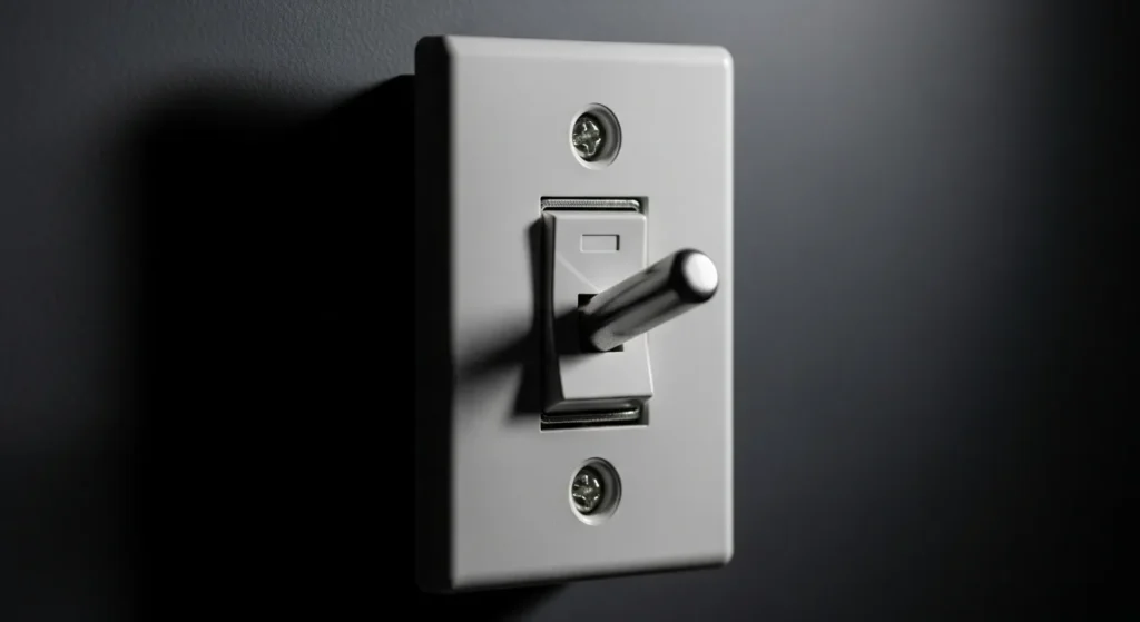
Fig 1. Two-way switch wiring two switches connected by traveler wires controlling a single light fixture from two separate locations. The circuit behaves as an XOR logic gate: light ON when both switches are in the same position.
What Every Electrician and DIYer Must Know
Two-way switching is a physical implementation of the XOR (Exclusive OR) logic gate. Light = ON only when Switch 1 position XOR Switch 2 position = 1. This is the elegance that makes the circuit work pure Boolean logic realized in copper and contacts.
LED drivers exhibit 8–12× rated current inrush for 10–20 ms at startup. A standard 10A switch rated for resistive loads may only handle 3–5A for inductive/capacitive loads under IEC 60947-5-1. Always use LED-rated switches for LED lighting circuits.
Long traveler runs in hotels and corridors cause significant voltage drops. At 0.8A through 20m of 1.5mm² copper, the drop is 0.186V acceptable. But at 5A through 20m, the drop is 1.16V (9.7% of 12V supply) causing LED dimming and heat in wires.
NEC 404.2 and IEC wiring standards prohibit switching in the Neutral conductor. Doing so leaves the fixture energized even when the switch is “off” creating lethal shock hazard when replacing bulbs. ALL switching must occur in the Line (Hot/Phase) conductor only.
Most smart switches require: (1) a neutral wire at the switch box, (2) specific multi-way firmware/models. Standard two-way wiring often lacks neutral in the switch box requiring rewiring or a no-neutral smart switch (limited options, some reliability trade-offs).
The protective device (MCB/fuse) MUST trip under fault conditions. If circuit loop impedance Zs is too high (long cables, poor joints), fault current may not reach the trip threshold leaving the circuit “protected” by a breaker that won’t actually trip. Test with a loop impedance tester before commissioning.
What Is a Two-Way Switch and How Does It Work?
A two-way switch is an electrical switch with three terminals (COM, L1, L2) that allows a single light or load to be controlled from two separate locations. The most familiar example is a staircase light: turn it on from the bottom, turn it off at the top without retracing your steps. This is achieved by connecting two two-way switches with “traveler” wires that create two alternative current paths between them.
The operating principle is a direct implementation of the XOR (Exclusive OR) logic gate: the light is ON only when both switches are connected to the same traveler wire. When they connect to different travelers, the circuit is broken and the light is OFF. Flipping either switch changes the state exactly like XOR logic where the output changes when either input changes.
Table of Contents
- → What Exactly Is a 2-Way Switch?
- → How Does It Work? XOR Logic Principle
- → Why Would You Need This Setup?
- → Wiring Methods: 3-Wire vs 2-Wire Explained
- → Complete Wiring Diagram Step by Step
- → Can You Do This Yourself? DIY Safety Guide
- → Choosing the Right Switch Brand Guide & Ratings
- → Advanced Topics: Voltage Drop, Inrush Current & Loop Impedance
- → Load Calculation & Wire Sizing
- → Smart Switch Compatibility in Two-Way Setups
- → Wiring Standards: IEC 60669, NEC 404.2 & Wire Color Codes
- → Common Problems & Fixes: Diagnostic Troubleshooting
- → Frequently Asked Questions (FAQ)
What Exactly Is a 2-Way Switch?
You have probably seen them before those unassuming switches on the wall that look like any other. But here is the twist: a two-way switch is part of a clever system that lets you turn a single light on or off from two different locations. Think of it like having two volume buttons on your phone one on each side. No matter which hand you use, you can adjust without fumbling around.
A two-way switch differs from a standard one-way switch in one fundamental way: it has three terminals instead of two, allowing current to flow in different directions depending on switch position. This three-terminal design is what appears in every 2-way switch wiring diagram and two-way electrical switch wiring diagram each terminal plays a specific, non-interchangeable role.
This setup is sometimes called a “staircase switch” because it is most commonly used on staircases controlling the light from both the top and the bottom. But the name undersells its versatility: two-way switches are used in bedrooms, hallways, garages, offices, and any space where controlling a light from two locations is more convenient or safer than a single switch.
How Does It Work? The XOR Logic Principle
The two-way switch system is an elegant application of selective path control, enabling operation of a single light from two separate locations. The entire circuit is based on the logic of either completing or breaking the circuit using two parallel routes traveler wires.
Here is the exact mechanism:
- Switch 1 (at bottom of stairs): Receives the permanent Line (Hot) power on its COM terminal. The internal contact can connect COM to either L1 or L2.
- Switch 2 (at top of stairs): Sends the output from its COM terminal to the light fixture. The internal contact can connect COM from either L1 or L2.
- Traveler wires: Two wires connecting L1 of Switch 1 to L1 of Switch 2, and L2 of Switch 1 to L2 of Switch 2. These are the two “lanes” electricity can travel between the switches.
Why Would You Need This Setup?
If you have ever walked into a long hallway, turned on the light, and then stood there wondering how to turn it off again without walking all the way back you already know the answer. Two switches, one light (also called “2 switches 1 light” or “1 light two switches”) is the practical solution. Here are the most common applications:
Staircases
The classic application turn the light on at the bottom of the stairs and off at the top (or vice versa). Eliminates the need to navigate stairs in the dark or retrace steps to reach a single switch.
Long Hallways
Turn the light on as you enter one end of a hallway and off as you exit the other end. No awkward walk back to the first switch in the dark.
Bedrooms
Control the overhead light from both the door (when entering) and the bed (when ready to sleep). Perfect for lazy mornings, late-night bathroom trips, or any time you do not want to get out of bed again.
Garages
Turn on the garage light from inside the house before heading out, and turn it off once you are safely inside the car. Eliminates walking to the switch in the dark when car headlights are off.
Offices & Commercial
Control lighting in open-plan areas, conference rooms, or shared spaces from multiple entry/exit points. Reduces energy waste from lights left on in empty rooms.
Hotels & Hospitality
Bedside and door switches for room lights essential in hotel rooms where guests expect to control overhead lights from both the door and the bed without leaving comfort.
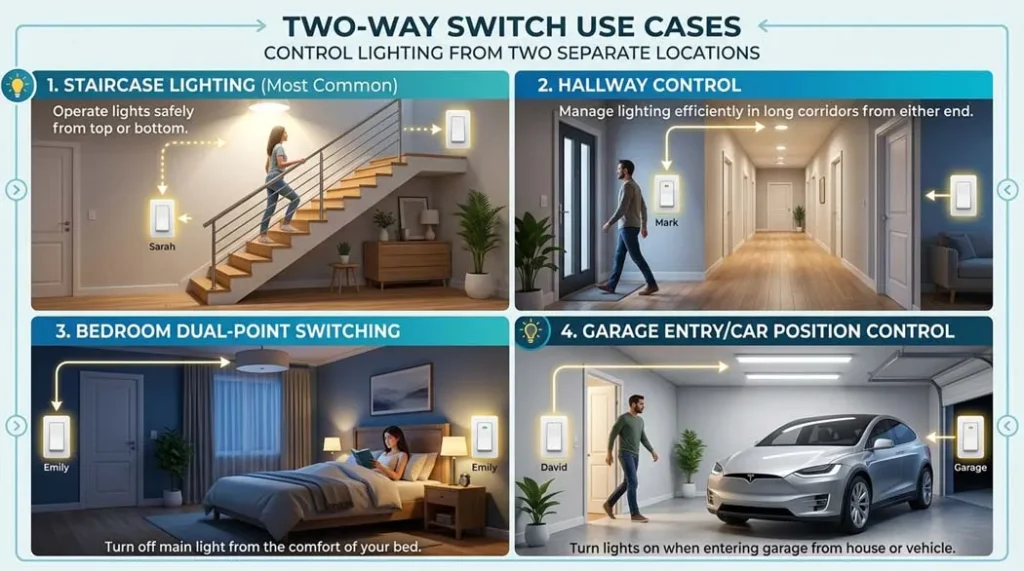
Fig 2. Two-way switch use cases staircase lighting (most common), hallway control, bedroom dual-point switching, and garage entry/car position control
Wiring Methods: 3-Wire vs 2-Wire Explained
There are two main methods for wiring a two-way switch. The three-wire method is the modern standard for all new installations; the two-wire method is an older approach still found in some existing installations.
The Three-Wire Method (Modern & Recommended)
This method uses three conductors between the switch boxes:
- Wire 1: Live/Line (from supply to COM of Switch 1)
- Wire 2 (Traveler L1): Connects L1 of Switch 1 to L1 of Switch 2
- Wire 3 (Traveler L2): Connects L2 of Switch 1 to L2 of Switch 2
- Switch Leg: From COM of Switch 2 to the light (the switched output)
- Neutral: Direct from supply to the light (bypasses both switches)
This method provides full control from either switch, is compatible with modern LED drivers, and is the only reliable method for retrofitting smart switches. It is the preferred option for all new residential and commercial installations and is shown in any modern 2 way switch wiring diagram.
The Two-Wire Method (Older Style)
The older two-wire method used only two conductors between the switch boxes limiting flexibility and making it harder to expand the circuit or add smart switches. It is still found in homes built before the widespread adoption of three-wire standards and is referenced in older connection diagrams of two way switch. While it functions correctly for simple on/off control, it is not suitable for modern smart switch retrofits that require a neutral wire at the switch box.
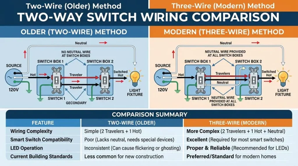
Fig 3. Two-wire (older) method vs three-wire (modern) method for two-way switch wiring. The three-wire method provides neutral at the switch box essential for smart switch compatibility and proper LED operation.
| Feature | Three-Wire Method (Modern) | Two-Wire Method (Older) |
|---|---|---|
| Conductors between boxes | 3 (Live + L1 + L2) | 2 (L1 + L2 only) |
| Neutral availability | Depends on routing can be brought to box | Typically not at switch box |
| Smart switch compatible | ✅ Yes (if neutral routed to box) | ❌ Usually no (no neutral) |
| LED compatibility | ✅ Full compatibility | ⚠️ May cause LED flicker |
| Recommended for new work | Yes always | No retrofit only |
| NEC/IEC compliance | ✅ Fully compliant | ✅ Compliant (if correctly wired) |
Complete Wiring Diagram Step by Step
The complete wiring sequence for the three-wire method:
- Supply Live → COM of Switch 1: The live (hot) wire from the supply enters the COM terminal of Switch 1
- L1 of Switch 1 → L1 of Switch 2: First traveler wire connects the L1 terminals of both switches
- L2 of Switch 1 → L2 of Switch 2: Second traveler wire connects the L2 terminals of both switches
- COM of Switch 2 → Light: The switched output leaves COM of Switch 2 and goes to the light fixture
- Supply Neutral → Light directly: The neutral wire bypasses both switches and connects directly to the light fixture
- Earth/Ground: Connected to switch metalwork and light fixture per local codes
Can You Do This Yourself? DIY Safety Guide
Turn Off Power and Verify
Switch off the correct circuit breaker at your consumer unit/panel. Use a non-contact voltage tester at BOTH switch locations to confirm zero voltage. Post a warning sign on the breaker panel while you work. Never rely on the switch position alone a two-way switch circuit may still have live conductors at both switch boxes even when the light is “off”.
Identify and Label Your Wires
Before disconnecting anything, photograph the existing wiring from multiple angles. Label each wire with tape (Live, L1, L2, Neutral, Earth). In older installations, wires may be incorrectly identified by color always verify with a continuity tester before connecting. In NEC installations, any white wire used as a switched leg must be re-identified with black or red tape.
Connect Switch 1
Connect the Live (Line/Hot) wire to the COM terminal. Connect Traveler 1 to L1. Connect Traveler 2 to L2. Connect earth to the earth terminal. Do not overtighten terminal screws tighten to the torque specified on the switch (typically 0.5–1.0 Nm). Check each connection is secure with a gentle tug.
Connect Switch 2
Connect Traveler 1 to L1. Connect Traveler 2 to L2. Connect the switch leg wire (going to the light) to COM. Connect earth. Again, verify all connections are correct against the wiring diagram before proceeding. The most common mistake is swapping COM and a traveler terminal on Switch 2.
Connect the Light Fixture
Connect the switch leg (from COM of Switch 2) to the Live terminal of the light. Connect Neutral directly from supply to the Neutral terminal of the light. Connect Earth. Ensure the lamp/fitting is correctly rated for your supply voltage (230V IEC or 120V NEC).
Test Before Closing
Before replacing faceplates, restore power at the breaker. Test all four switch positions: SW1-up/SW2-up (ON or OFF), SW1-up/SW2-down (opposite), SW1-down/SW2-up (opposite), SW1-down/SW2-down (ON or OFF). Confirm light responds correctly from both switches. If only one switch works, recheck traveler connections at both boxes.
Safety Rules Never Compromise These
- Always turn off power first and verify with a tester before touching any wire
- Use insulated tools rated for your supply voltage (1000V rated for safety margin)
- Wear protective gloves when working near live equipment
- Keep your workspace dry never work in wet or damp conditions
- Do not overload the circuit check total wattage against breaker rating
- Never force wires into tight connections this causes high-resistance joints that overheat
- Call a licensed electrician if unsure at any point there is no shame in professional help for safety-critical work
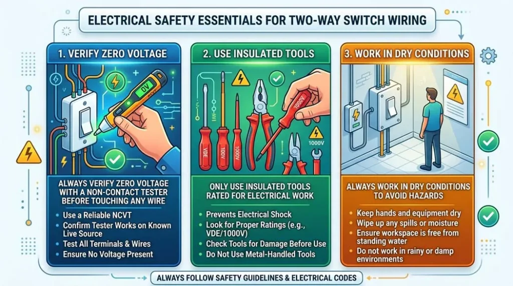
Fig 4. Electrical safety essentials for two-way switch wiring always verify zero voltage with a non-contact tester before touching any wire, use insulated tools, and work in dry conditions.
Choosing the Right Switch Brand Guide & Ratings
Not all switches are created equal. In India and internationally, some trusted brands offer high-quality two-way switches that work well in setups like 2 lights to one switch or 1 light two switches, combining durability with safety. Key specifications to verify:
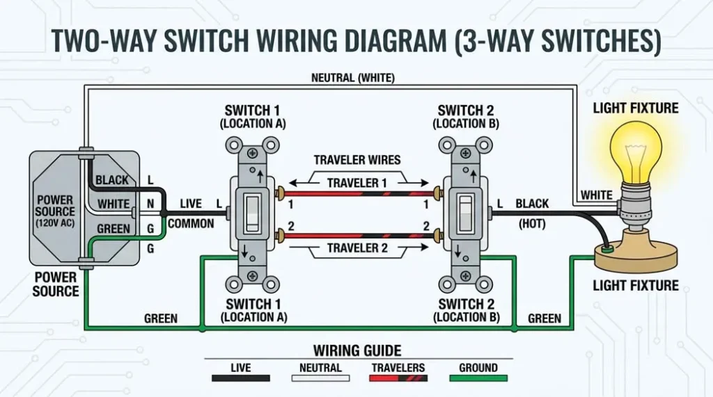
Fig 5. Quality two-way switches modular designs from trusted brands. For LED circuits, always verify the switch has an LED-compatible rating to prevent flickering and premature contact wear.
| Brand | Model | Current Rating | Notes |
|---|---|---|---|
| Legrand | White Legrand Britzy | 16 Amp | IEC certified, LED compatible, excellent build quality |
| Maddox | White Modular Two-Way Switch | 16 Amp | Reliable modular design, good contact rating |
| Schneider Electric | Two-Way Modular Switch | 10 Amp | International brand, IEC compliant, CE marked |
| Affonso | Modular Switch | 10 Amp | Budget-friendly, suitable for standard lighting loads |
| Arcitech | 2-Way Electrical Switch | 6 Amp | For low-load lighting only; verify LED compatibility |
Switch Selection Criteria
- Current Rating: Must exceed the calculated load current by 125% safety margin. For a 1000W load on 230V: I = 1000/230 = 4.35A → minimum 6A switch, recommended 10A+
- Load Type Rating: Standard switches are rated for resistive loads. For LED or CFL drivers (capacitive/electronic loads), de-rate by 30–50% or use specifically LED-rated switches per manufacturer specification
- Safety Certification: Look for ISI mark (India), CE mark (Europe), UL listing (USA/Canada), and IEC 60669 compliance stamped on the switch body
- Voltage Rating: Must match your supply voltage 230V for IEC/India/Europe, 120V for NEC/USA
- Terminal Type: Screw terminals allow re-tightening over time; push-in terminals are faster to install but harder to inspect for loose connections
Advanced Topics: Voltage Drop, LED Inrush & Loop Impedance
Voltage Drop Calculation for Long Traveler Runs
Long traveler runs in hotels, commercial corridors, or large homes can significantly reduce delivered voltage to LED drivers causing dimming, flickering, or code non-compliance. The voltage drop must be calculated and kept below 3% for most codes.
ρ = Resistivity (copper: 0.0175 Ω·mm²/m) | L = One-way wire length (m) | A = Cross-section area (mm²)
For round-trip (both traveler wires): Rtotal = ρ × 2L / A
Keep ΔV ≤ 3% of supply voltage (≤ 6.9V on 230V; ≤ 3.6V on 120V)
20m Traveler Run, 0.8A LED Driver, 1.5mm² Cable
Wire resistance: R = ρ × L / A = 0.0175 × 20 / 1.5 = 0.233 Ω (one way)
Round-trip resistance: Rtotal = 2 × 0.233 = 0.467 Ω
Voltage drop: ΔV = 0.8A × 0.467Ω = 0.374 V
Percentage drop: 0.374/230 × 100% = 0.16% well within 3% limit ✓
Heavy load comparison (5A, 20m): ΔV = 5A × 0.467Ω = 2.33V = 1.01% still acceptable ✓
When to upsize: If voltage drop exceeds 3% (6.9V on 230V), upsize to 2.5mm² cable. Rnew = 0.0175 × 20/2.5 = 0.14Ω per conductor → ΔV at 5A = 5 × 0.28 = 1.4V = 0.61% ✓
LED Driver Inrush Current
Modern two-way circuits often drive LED drivers, which exhibit significantly higher inrush currents than their steady-state rating suggests:
Duration: 10–20 milliseconds (very brief but can damage contacts)
Example: 10W LED driver at 230V: Irated = 10/230 = 0.043A → Iinrush ≈ 0.35–0.52A peak
For 20 × 10W drivers: Iinrush ≈ 7–10A could exceed a 6A switch rating!
Fix: Use AC-15 (IEC 60947-5-1) or LED-specifically rated switches
Neutral and Switching Method Matrix
| Topology | Description | Smart Switch Note |
|---|---|---|
| Switch-leg without neutral | Only line and switched leg present at switch box | ❌ Not suitable for most smart switches |
| Neutral at fixture only | Neutral terminated at light fitting, not switch box | Requires rewiring to bring neutral to box for smart switch |
| Neutral in switch box | Line, neutral, and switched leg all present in switch box | ✅ Fully compatible with smart switches |
Contact Rating vs Load Type
| Load Type | Contact Wear Risk | Recommendation |
|---|---|---|
| Resistive (incandescent) | Low predictable current profile | Standard switch rating OK |
| Inductive (motors, transformers) | Medium inductive kick on opening | Use AC-15 rated switch (IEC 60947-5-1) |
| Electronic drivers (LED, CFL) | High high inrush, capacitive load | De-rate 30–50% or use LED-rated switch |
| Large LED array (20+ drivers) | Very high cumulative inrush | Use contactors or relay with LED-rated coil controller |
Safety Threshold: Loop Impedance
Ia = Fault current required to operate the protective device within specified time
Example: 230V supply, 16A MCB (Ia = 160A for 0.4s disconnect): Zs ≤ 230/160 = 1.44 Ω max
Excessive Zs means the MCB will NOT trip under fault → live parts remain energized → electrocution risk
Always test with a loop impedance tester before commissioning in commercial/industrial settings
Load Calculation & Wire Sizing
Professional installation of a two-way circuit requires proper load calculations to determine wire gauge and switch rating. Both must exceed the calculated value by a 125% safety margin.
Safety margin: Minimum switch/wire rating = Itotal × 1.25
Example: 500W of LED lighting at 230V → I = 500/230 = 2.17A → minimum 2.17×1.25 = 2.72A → use 6A switch + 1.5mm² wire
For 2000W load at 230V → I = 8.7A → minimum 10.9A → use 16A switch + 2.5mm² wire
| Load (W) @ 230V | Current (A) | Min Switch Rating | Wire Size (IEC) | Wire Size (NEC) |
|---|---|---|---|---|
| 100W (1 × bulb) | 0.43A | 6A | 1.0 mm² | 14 AWG |
| 500W (5 × 100W equiv.) | 2.17A | 6A | 1.5 mm² | 14 AWG |
| 1000W (10 × 100W equiv.) | 4.35A | 6A | 1.5 mm² | 14 AWG |
| 2300W (max 10A circuit) | 10A | 16A | 2.5 mm² | 12 AWG |
| 3600W (max 16A circuit) | 15.65A | 20A | 2.5 mm² | 12 AWG |
Smart Switch Compatibility in Two-Way Setups
Smart switches in two-way configurations require specific planning. There are several approaches, each with trade-offs:
| Approach | Description | Neutral Required? | Pros | Cons |
|---|---|---|---|---|
| Main Smart + Auxiliary | One smart switch at one location; a simple auxiliary remote at the other | ✅ At main switch only | One smart switch, lower cost | Auxiliary must be manufacturer-matched |
| Two Smart Switches | Full smart switch at both locations requires specific multi-way firmware | ✅ At both boxes | Full smart control from both | Higher cost; neutral must be at both boxes |
| No-Neutral Smart Switch | Uses tiny current through the load to power itself (no neutral needed) | ❌ Not required | Works with existing wiring | May cause LED flicker; load must be compatible |
| Wireless Remote System | One standard smart switch; wireless remote at the other location | ✅ At switch box | No traveler wire extension needed | Batteries in remote; RF/WiFi reliability |
Wiring Standards: IEC 60669, NEC 404.2 & Wire Color Codes
International and National Standards
- IEC 60669 (Switches for Household and Similar Fixed Electrical Installations): Governs the testing and functional requirements for all two-way and one-way switches including contact rating, breaking capacity, temperature rise under load, mechanical and electrical endurance cycles, and IP protection ratings. Compliance ensures the switch can reliably break the circuit under fault and inrush conditions.
- NEC 404.2 (US National Electrical Code Switches): Mandates that all switching must occur only in the Line (Hot) conductor. Switching the Neutral conductor is strictly prohibited because it leaves the fixture energized even when the switch is “off” creating fatal electrocution hazard when replacing bulbs or servicing the fitting.
- Wire Sizing: NEC Table 310.16 and IEC 60364-5-52 provide ampacity tables specifying minimum wire gauge based on breaker rating, ambient temperature, grouping/bundling factors, and installation method (conduit, trunking, buried, exposed).
Wire Color Codes IEC vs NEC
| Conductor | IEC / UK / EU / India | NEC / USA / Canada | Critical Rule |
|---|---|---|---|
| Line / Hot / Phase | Brown (or Black in older) | Black or Red | Always switched. Never connect to Neutral-colored wire without re-identification |
| Neutral | Blue | White (or Gray) | Never switched. Goes directly to load. Re-identify any Neutral used as switched conductor |
| Earth / Ground | Green-Yellow striped | Green or Bare copper | Never carry load current. Must be continuous and properly bonded |
| Travelers (L1, L2) | Brown or Black (must be clearly identified as switched live) | Black or Red (re-identify white with tape if used) | Both are treated as Live conductors handle accordingly |
Common Problems & Fixes: Diagnostic Troubleshooting
🏁 Final Thoughts: It’s Not Just About the Light
Two-way switch wiring is more than just a technical detail it is about making your home smarter, safer, and more convenient. Whether you are installing it for the first time or upgrading an old system, understanding the XOR logic principle, the three-wire method, voltage drop calculations, inrush current requirements, and compliance with IEC 60669 and NEC standards puts you in control literally and professionally.
The elegance of a two-way switch lies in its simplicity: two switches, two traveler wires, one light and the same principles that describe its behavior also describe the XOR logic gate inside every digital processor. Electronics and electrical engineering share the same foundational logic, just realized at different scales.
Take your time, follow the steps, prioritize safety, and soon enough you will be flipping switches like a pro from either end of the hallway. And if you ever feel overwhelmed remember: every expert was once a beginner. Call a licensed electrician when in doubt, and share your results in the comments below!
❓ Frequently Asked Questions (FAQ)
Yes, but with important considerations. Ensure the switch’s rating is compatible with the LED driver’s inrush current LED drivers exhibit 8–12× rated current inrush for 10–20 ms at switch-on. With large banks of LEDs, cumulative inrush can exceed a standard switch’s contact rating, causing premature contact welding or wear. Use switches specifically rated for LED/electronic loads, or switches compliant with IEC 60947-5-1 (AC-15 rating). Additionally, some switch types have small residual currents when “off” that can cause LED ghost illumination use a switch designed for LED loads or add a LED-specific capacitive filter at the fitting.
There is no electrical difference the terms are regional conventions: “Two-way” is the standard term in IEC/UK/EU/Australia/India standards, referring to a switch with 3 terminals (COM, L1, L2) controlling a load from 2 locations. “Three-way” is the standard term in NEC/USA/Canada standards, referring to the same circuit configuration and the same physical switch (also 3 terminals). Both refer to a circuit controlling a single load from two separate switch locations using traveler wires. When a third location is added, IEC adds an “intermediate” switch while NEC adds a “four-way” switch but the underlying circuit principle remains the same.
Traveler wires carry the switched Line/Phase voltage between the L1 and L2 terminals of the two switches. In NEC systems: travelers are typically Black or Red wires. If a white wire is used as a traveler (older construction), it must be re-identified with black or red tape at both ends to indicate it carries switched hot voltage not neutral. In IEC systems: travelers are typically Brown or Black (same color as Live/Phase), but are identified by their function connecting the L1 and L2 terminals. The key rule in both systems: all traveler wires carry live/hot voltage and must be treated as live conductors during all inspection and maintenance work.
COM stands for Common the main terminal through which the circuit’s primary conductor always passes, regardless of switch position. On Switch 1 (supply side): COM receives the permanent Line/Hot power from the supply. On Switch 2 (load side): COM sends the switched power output to the light fixture. Between the two COMs, the traveler wires (L1 and L2) provide the two alternative paths. The internal contact mechanism moves between L1 and L2 when you flip the switch but COM always remains connected to whichever traveler the contact selects.
Yes. To control a light from three or more locations, you need to add one or more four-way (IEC: intermediate) switches between the two two-way switches. The circuit remains the same at the ends both end switches are standard two-way switches connected with COM and travelers. Each intermediate position adds a four-way switch that crosses or passes the two traveler wires. Adding one four-way switch gives 3-location control; two four-way switches give 4-location control and so on. This is called multiway switching and is used in long hallways, large conference rooms, hotel corridors, and commercial spaces.
Incorrect traveler connections cause predictable symptoms: (1) Light works from only ONE switch typically means one traveler is disconnected or connected to wrong terminal at one box. (2) Light doesn’t work at all both travelers may be crossed, or one connected to Neutral. (3) Light is always on regardless of switch position Live wire connected to the light side bypassing the switching circuit. The diagnostic method: with power OFF, use a continuity tester to verify L1 at SW1 connects to L1 at SW2 (and separately L2 to L2). Any open circuit or cross-connection in traveler paths explains the fault.
Yes, but you need switches specifically designed for multi-way setups. Options include: (1) Main smart switch + auxiliary remote one smart switch at one location, manufacturer-matched auxiliary at the other. (2) Two smart switches with multi-way firmware requires neutral at both boxes. (3) No-neutral smart switch uses tiny current through load to power itself (may cause LED flicker). (4) Wireless remote system smart switch at one location, RF/WiFi remote at the other. Always check manufacturer specifications for multi-way compatibility before purchasing, and verify neutral wire availability in your switch boxes.
Buzzing or heating indicates one of these problems: (1) Overloaded switch total load current exceeds the switch’s rating. Calculate load: I = P/V and verify the switch rating exceeds I × 1.25 safety margin. (2) Loose connections even slightly loose terminals cause arcing at the connection point, generating heat and electromagnetic noise. Tighten all terminal screws and re-verify. (3) Load type incompatibility LED or CFL drivers on a resistive-only rated switch cause contact stress due to inrush and non-sinusoidal current waveforms. Replace with LED-compatible or AC-15 rated switch. (4) Contact contamination carbonized contacts from repeated arcing must be replaced (cannot be cleaned reliably).
Wire size depends on load current and run length. For most residential lighting: 1.5 mm² (14 AWG) for circuits up to 10-16A breaker on lighting circuits with short runs. 2.5 mm² (12 AWG) for higher loads, longer runs (over 15m traveler distance), or where voltage drop calculations show 1.5mm² would exceed 3% drop. Always follow local electrical codes IEC 60364-5-52 (international) or NEC Table 310.16 (USA) for exact requirements based on your installation method, ambient temperature, and grouping factor. When in doubt, upsize: larger wire always complies and never causes problems.
Yes, but it requires additional wiring work: (1) Install a new two-way switch at the second desired location. (2) Run a 3-core cable between the two switch locations (for Live, L1 traveler, L2 traveler plus Earth). (3) Replace the existing one-way switch with a two-way switch. (4) Rewire both switch boxes: COM at Switch 1 gets the Live; L1/L2 connect to the traveler wires; COM at Switch 2 connects to the light. (5) Verify all connections against a wiring diagram before restoring power. The main challenge is routing new cable between the switch locations in existing construction, this may require lifting floorboards, removing plasterwork, or routing through conduit/trunking.
Yes wireless options eliminate the need to run new traveler cables between locations: (1) RF remote switches battery-operated remote controls a standard switch; no wiring between locations needed. (2) Smart home systems (WiFi/Zigbee/Z-Wave) apps, voice control, and physical smart switches work together; requires home network. (3) Wireless kinetic switches self-powered by press action (piezoelectric), no batteries needed, RF signal to smart receiver. These are excellent retrofit solutions for locations where running new cable is impractical, but require power at the main switch location and consideration of RF/WiFi reliability in your building.
Look for these marks before purchasing: ISI mark (India Bureau of Indian Standards certification), CE mark (Europe indicates conformity with EU directives including Low Voltage Directive), UL listing (USA/Canada Underwriters Laboratories safety testing), IEC 60669 compliance (international standard for household switches contact rating, endurance, safety), and your country’s voltage rating stamped on the device (230V for IEC regions, 120V for NEC regions). Avoid unbranded or uncertified switches they may fail under fault conditions or inrush current, causing fire hazards without the protection certification provides.
Most smart switches require a neutral wire to power their internal electronics (WiFi/Zigbee radio, microprocessor, relay). Without neutral, the switch has no return path for its own power supply. In many older installations (particularly UK/EU two-way circuits), the neutral is only at the light fitting not in the switch box. Options if neutral is absent: (1) Rewire to bring neutral to the switch box the correct long-term solution. (2) Use a “no-neutral” smart switch available from Shelly, Sonoff, and others but may cause LED flickering or ghost illumination due to the small bypass current required. (3) Use a wireless battery-powered remote paired with a smart receiver at the load avoids the neutral requirement entirely.
📚 Continue Learning on Procirel
📎 Technical References & Standards
- 1IEC 60669-1:2017 Switches for Household and Similar Fixed Electrical Installations General Requirements IEC Contact rating, endurance, safety requirements for two-way switches [International Standard]
- 2NEC 404.2 National Electrical Code Switches: General NFPA Prohibition on switching Neutral conductors; switching only in Line conductor [US National Standard]
- 3IEC 60947-5-1:2016 Low-Voltage Switchgear and Controlgear Control Circuit Devices and Switching Elements IEC AC-15 contact rating for inductive/electronic loads including LED drivers [International Standard]
- 4BS 7671:2018+A2:2022 Requirements for Electrical Installations (IET Wiring Regulations, 18th Edition) IET/BSI UK wiring regulations including two-way switch circuit design and loop impedance requirements [UK National Standard]
- 5IEC 60364-5-52:2009 Electrical Installations of Buildings Selection and Erection of Electrical Equipment Wiring Systems IEC Wire sizing and ampacity tables for switching circuit conductors [International Standard]
- 6NEC Table 310.16 Allowable Ampacities of Insulated Conductors Rated 0–2000 Volts NFPA Wire gauge selection for two-way switch circuits under NEC jurisdiction [US National Standard]
- 7IEC 60669-2-1:2009 Switches Electronic Switches IEC Requirements for electronic and smart switches including no-neutral and LED-compatible types [International Standard]