Introduction: Understanding the Foundation of Digital Circuits
A digital system is built on logical decisions. At the heart of these decisions lies the Sum of Products (SOP) form. SOP is not just an algebraic notation—it is the foundational blueprint for two-level logic circuit implementation across all modern digital electronics, from basic microcontrollers to advanced FPGAs. Mastering SOP is the first step toward efficient, high-speed circuit design.
Have you ever wondered how your computer makes decisions? Behind every digital device we use daily from smartphones to laptops to smart
home devices lies a complex network of circuits built on simple logical operations. At the heart of these operations is a concept known as the sum of
products. The sum of products is a fundamental concept in digital logic design that represents Boolean functions as a logical OR of AND terms.
It’s one of those ideas that might seem abstract at first, but once you grasp it, you’ll see how it shapes the digital world around us.
In this guide, I’ll walk you through everything you need to know about sum of products expressions from basic definitions to practical applications. Whether you’re a student struggling with digital electronics homework, an engineer looking to refresh your knowledge, or just someone curious about how computers “think,” this article has something for you.
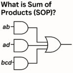
What is Sum of Products (SOP)?
Sum of products (SOP) is a way to express Boolean functions in digital logic. Despite its mathematical-sounding name, the concept is actually quite straightforward. In Boolean algebra, a sum of products expression consists of multiple AND terms (products) combined using OR operations (sums). Each product term is made up of variables or their complements ANDed together. For example, a simple SOP expression might look like:
F = A·B + A’·C
In this expression:
- – A·B is one product term (A AND B)
- – A’·C is another product term (NOT A AND C)
- – The plus sign represents the OR operation
When implementing digital circuits, the sum of products form provides a standardized approach to converting truth tables into logical expressions. This makes it an essential tool in the digital designer’s toolkit.
Minterms: The Building Blocks of SOP
To truly understand SOP, we need to talk about minterms. A minterm is a product term where each variable appears exactly once, either in its normal or complemented form. For a function with n variables, there are 2^n possible minterms. Each minterm corresponds to exactly one row in a truth table where the output is 1. For example, with three variables (A, B, C), the minterm m₃ (which is binary 011) would be written as A’·B·C. This minterm is true only when A=0, B=1, and C=1. Understanding how to derive the sum of products from a truth table is essential for digital electronics students. Let’s look at how to do this with a simple example.
How to Calculate Sum of Products from a Truth Table
Learning how to calculate sum of products expressions starts
with identifying the minterms from a truth table. Let’s walk through this
process step by step:
Create: a truth table for your Boolean function
Identify: all rows where the output is 1
Write: the minterm for each of these rows
Combine: all minterms with OR operations
Let’s try an example with a three-variable function: Looking at this table, we see that F=1 when:
- – A=0, B=0, C=1 (minterm m₁)
- – A=0, B=1, C=1 (minterm m₃)
- – A=1, B=0, C=0 (minterm m₄)
- – A=1, B=1, C=0 (minterm m₆)
So our SOP expression would be:
F = A’·B’·C +A’·B·C + A·B’·C’ + A·B·C’
Or using sigma notation:
F =Σm(1,3,4,6)
This sum of products tutorial example demonstrates the
direct relationship between truth tables and SOP expressions. Once you’ve
practiced this a few times, it becomes second nature.
Canonical and Non-Canonical Forms of SOP
When working with sum of products expressions, you’ll
encounter two main forms: canonical and non-canonical.
Canonical SOP Form
A canonical SOP expression (also called the “standard” form)
includes all variables in each product term. This means that for a function
with n variables, each product term contains exactly n literals. The canonical
form directly corresponds to the minterms from a truth table. It’s complete and
unambiguous, but often not the most efficient representation. For example, the
canonical SOP form of a function might be:
F = A’·B’·C +A’·B·C + A·B’·C’ + A·B·C’
Non-Canonical SOP Form
A non-canonical SOP expression is any SOP expression where
at least one product term doesn’t include all variables. These forms are
typically the result of simplification. For example, the above canonical
expression might simplify to:
F = B’·C’ + A’·C +A·B
This non-canonical form is more compact and would require
fewer gates to implement, making it preferable for practical circuit design. Understanding
these canonical forms is crucial for digital logic design, as they provide a
standardized starting point for circuit optimization.
Quantifying Optimization: Formulas for Minimal SOP Design
The transition from a canonical SOP expression to a minimal SOP (MSOP) is driven by three quantifiable engineering goals: lower cost, higher speed, and reduced power consumption.
1. Standard Notation and Canonical Form
A Boolean function $F$ for three variables ($A, B, C$) is defined by the specific minterms ($m$) that result in a logical ‘1’ output. This is the starting point for every design:
F ( A,B,C ) = ∑ m ( mi , mj , … ) e.g., F ( A,B,C ) = ∑ m ( 1,3,5,7 )
2. Gate Cost Formula (Area and Complexity)
The simplest way to calculate the cost (or size) of an SOP implementation is by summing the total number of inputs required for all AND and OR gates. Minimization directly reduces this cost:
Gate Cost = ∑ ( Inputs per AND Gate ) + ( Inputs for the Final OR Gate )
3. Propagation Delay (t_pd) (Speed)
SOP is a fast two-level logic circuit. The total time delay is approximately the delay through one AND gate and one OR gate. Simplification often allows for the use of faster, smaller gates, which minimizes the overall propagation delay, $t_{pd}$:
t pd ≈ t AND + t OR
Difference Between Sum of Products and Product of Sums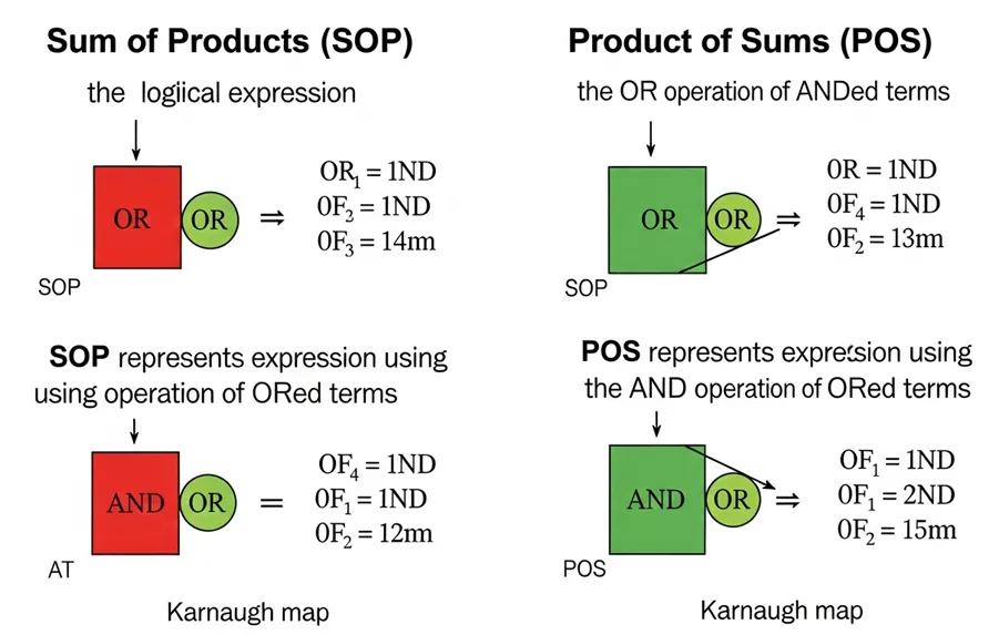
The fundamental difference between sum of products and product of sums lies
in their logical structure and implementation.
Sum of Products (SOP)
ü Structure: OR of AND terms
ü Based on: Minterms (combinations that make the function true)
ü Circuit implementation: AND gates feeding into OR gates
ü Truth table derivation: Focus on rows where output is 1
Product of Sums (POS)
· Structure: AND of OR terms
· Based on: Maxterms (combinations that make the function false)
· Circuit implementation: OR gates feeding into AND gates
· Truth table derivation: Focus on rows where output is 0
Understanding the difference between sum of products and
product of sums helps in choosing the most efficient implementation for a
specific circuit. Sometimes one form leads to a simpler circuit than the other.
For example, the function we derived earlier as F = A’·B’·C + A’·B·C + A·B’·C’ + A·B·C’
Could be expressed in POS form as:
F =(A+B+C)·(A+B+C’)·(A+B’+C)·(A’+B+C)·(A’+B’+C’)
Depending on the specific function and available components,
one form might be more practical than the other.
SOP vs. POS: Side-by-Side Comparison
The choice between Sum of Products (SOP) and Product of Sums (POS) depends on which form results in fewer, simpler gates for a given function.
| Feature | Sum of Products (SOP) | Product of Sums (POS) |
|---|---|---|
| Definition | A logical OR (Sum) of AND terms (Products). | A logical AND (Product) of OR terms (Sums). |
| Truth Table Basis | Focus on 1 outputs (Minterms). | Focus on 0 outputs (Maxterms). |
| Implementation | AND-OR Two-Level Logic. | OR-AND Two-Level Logic. |
| Example | F = AB + A ′ C | F = ( A + B ) ( A ′ + C ) |
Simplifying Boolean Expressions Using Sum of Products
Once you have a canonical SOP expression, the next step is often
simplification. Simplifying Boolean expressions using sum of products can
significantly reduce the number of gates needed in your circuit. There are
several methods for simplification:
1. Boolean Algebra Laws
Boolean algebra provides the mathematical foundation for
working with sum of products expressions in digital logic. By applying laws
such as:
o Idempotent Law: A + A = A and A · A = A
o Complementary Law: A + A’ = 1 and A · A’ = 0
o Absorption Law: A + (A · B) = A and A · (A + B) = A
You can often simplify expressions by hand. For example: F = A’·B’·C + A’·B·C Can be simplified to:F = A’·C·(B’ + B)= A’·C·1 = A’·C
2. Karnaugh Maps
A Karnaugh map offers a visual method for simplifying sum of products expressions by identifying adjacent minterms. This technique is especially powerful for functions with up to 5-6 variables. Digital designers often use the Karnaugh map technique to find the minimal sum of products form of a Boolean function. The process involves:
Creating: a grid where each cell represents a minterm Marking: cells where the function is true Grouping : adjacent marked cells in powers of 2 (1, 2, 4, 8, etc.)
Deriving : simplified terms from each group
The process of grouping cells in a Karnaugh map directly corresponds to finding common terms in a sum of products expression. This visual approach often makes it easier to spot simplification opportunities that might be missed with algebraic methods.
3. Quine-McCluskey Algorithm
For functions with many variables, algorithmic approaches like Quine-McCluskey provide a systematic way to find the minimal SOP form. While
beyond the scope of this article, this method is important for complex digital systems where manual simplification becomes impractical.
Applications of Sum of Products in Digital Logic Design
In digital logic design, the sum of products approach is commonly used for implementing combinational circuits. Let’s explore some real-world applications:
1. Combinational Logic Circuits: SOP expressions are directly implementable as two-level AND-OR circuits, making them ideal for:
a. Decoders and encoders
b. Multiplexers and demultiplexers
c. Arithmetic circuits (adders, subtractors)
d. Comparators
For example, a 4-bit magnitude comparator can be implemented using SOP expressions to determine whether one number is greater than, equal to, or less than another.

2. Programmable Logic Devices
Modern programmable logic devices like FPGAs (Field-Programmable Gate Arrays) and CPLDs (Complex Programmable Logic Devices) often use sum-of-products structures internally. Their architecture is well-suited to implementing Boolean functions in SOP form.
3. Memory Address Decoding
In computer systems, address decoders use SOP logic to activate the correct memory chip based on the address lines. This is a perfect application for SOP because each memory chip needs to be activated for specific address combinations.
4. Error Detection and Correction
Digital communication systems use SOP-based circuits for error detection and correction. Parity generators and checkers, for instance, can be efficiently implemented using sum of products expressions. These examples of sum of products in digital logic demonstrate the versatility and importance of this concept in modern digital systems.
Case Studies: SOP in Critical Digital Applications
SOP is the primary implementation method for combinational logic in professional hardware design:
Case 1: Traffic Light Controller (Sequencing Logic)
A simple traffic light sequence requires a Boolean function to determine the next state based on the current state and a sensor input (e.g., car waiting). The entire **state machine’s next-state logic is often derived from a truth table and implemented as a minimal SOP expression. For instance, the function for turning the North light Green is: G N = C ¯ ⋅ P ⋅ T, where C is the Clock, P is the Presence Sensor, and T is the Timer output. This provides immediate, two-level logic control.
Case 2: FPGA Programming (Mapping Logic to LUTs)
In a Field-Programmable Gate Array (FPGA), the fundamental logic element is the Look-Up Table (LUT). Modern FPGAs use 4- or 6-input LUTs. The synthesis tool takes the SOP expression derived from your VHDL/Verilog code and maps the entire MSOP function into these specific LUTs. This process is direct: each product term maps to a specific part of the LUT’s function, which reinforces why minimizing the number of inputs (literals) is critical for fitment and efficiency.
Case 3: Error Detection (Parity Generation)
Circuits for error detection, such as Parity Generators, use SOP. A simple odd-parity generator for 3-bits ($A, B, C$) outputs a ‘1’ when the number of 1s in the input is odd. This logic can be derived from a truth table and implemented in SOP form, though it often results in a XOR-gate chain for maximum efficiency, which is mathematically equivalent to a specific SOP expression.
SOP Troubleshooting: Avoiding Beginner and Professional Mistakes
Troubleshooting digital logic involves fixing simple algebraic errors and managing complex physical hardware constraints.
Common Beginner Mistakes & Algebra Fixes
- Mistake: Confusing SOP with POS. Using the ‘0’ outputs in the truth table to form a Sum of Products expression. Fix: SOP always corresponds to the 1 outputs (minterms, ∑m). Mistake: Forgetting to Include All Minterms. Missing a row with a ‘1’ output when translating a truth table to the canonical form. Fix: Double-check that the final ∑m notation includes every index where F=1. Mistake: Misapplying DeMorgan’s Laws. Incorrectly simplifying or converting between SOP and POS (e.g., forgetting to double-complement inputs). Fix: Remember: (A+B) ′= A′ ⋅ B′ (The sum complement equals the product of complements).
Advanced Troubleshooting: Hardware Constraints
- Issue: Fan-In Constraint Violation. The simplified SOP term requires more inputs than the physical AND gate can accept (e.g., 10 inputs for a 4-input gate). Fix: Implement the logic using a Multi-Level Logic structure (e.g., cascading two AND gates) or use a wider LUT if available on the FPGA. Issue: Dynamic Hazards/Glitches. The MSOP form creates a momentary output spike during input changes (due to propagation delay mismatch). Fix: Use a K-Map to identify the hazard region and add a redundant prime implicant (an extra K-Map group) to ensure the output remains stable during the input transition.
Tools and Software for SOP Implementation
several tools can help you work with sum of products expressions:
1. Logic Circuit Simulators
Logisim : An educational tool for designing and simulating digital logic circuits. It allows you to create circuits using AND, OR, and NOT gates to implement SOP expressions. CircuitVerse : An online platform for digital logic design with a user-friendly interface. Digital Works: A comprehensive digital logic simulator that
supports hierarchical designs.
2. Hardware Description Languages (HDLs)
Verilog and VHDL: Industry-standard HDLs that allow you to describe digital circuits at various levels of abstraction. You can directly implement SOP expressions in these languages. SystemVerilog: An extension of Verilog with additional features for verification and modeling.
3. Boolean Expression Calculators
Wolfram Alpha: Can simplify Boolean expressions and convert between different forms. Boolean Algebra Calculator: Online tools specifically designed for Boolean
algebra operations. K-Map Minimizer: Web applications that generate Karnaugh maps and find minimal SOP expressions. These tools make working with SOP expressions more efficient and less error-prone, especially for complex functions.
Future Trends in Digital Logic Design
Digital logic design is evolving with key trends shaping its future:
- AI & Machine Learning – Specialized circuits now optimize Boolean functions for neural networks, though most executives admit their infrastructure isn’t yet ready for rapid AI adoption.
- Quantum Interfaces – Classical logic must connect with quantum systems, driving new SOP forms for efficient communication.
- Low‑Power Design – Mobile and IoT demand energy‑efficient circuits, renewing interest in logic minimization.
- Advanced Synthesis Tools – Modern tools use sophisticated algorithms to automatically optimize Boolean functions beyond traditional SOP methods.
While SOP remains fundamental, its applications are expanding with AI, quantum computing, low‑power systems, and advanced synthesis technologies.
Industry Standards and SOP Implementation Compliance
Professional digital design is built on established standards that govern notation, synthesis, and physical characteristics.
1. Logic Notation and Symbols
- IEEE Std 91-1984: This standard defines the graphic symbols used for logic functions (AND, OR, NOT). Adhering to this standard is mandatory for creating clear, unambiguous circuit schematics and documentation.
- JEDEC Standards: Logic gates must comply with Joint Electron Device Engineering Council (JEDEC) specifications, which define physical characteristics like voltage levels ( VOH , VOL ) to ensure interoperability.
2. Synthesis and HDL Practices
In professional design, SOP is implemented using Hardware Description Languages (HDLs):
- Verilog/VHDL Coding: Engineers must write synthesizable code. While you don’t write the SOP equation directly, the case or if/else statements in your code are translated by the Logic Synthesis Tool into the most efficient MSOP (or POS) form for the target hardware.
- Technology Mapping: The final MSOP expression is mapped to the target hardware’s logic blocks (e.g., Look-Up Tables (LUTs) in an FPGA) during the synthesis phase.
Conclusion: Mastering the Foundation of Digital Logic
The Sum of Products (SOP) is a practical foundation of digital circuit design, used from simple logic gates to complex computer systems. SOP expressions standardize Boolean functions in hardware, helping you understand how digital systems work at their core. Learning to derive, simplify, and implement SOP builds insight into circuit design and computer architecture. Tools like Boolean algebra, Karnaugh maps, software, and hardware description languages each offer unique strengths, giving flexibility in solving problems. Whether you’re starting out or deepening your knowledge, mastering SOP equips you with essential skills for modern electronics.
Frequently Asked Questions (FAQ)
What is the fundamental difference between SOP and POS?
SOP (Sum of Products) is an OR of AND terms, derived from the 1 outputs (minterms) of a truth table, and is implemented as a two-level AND-OR circuit. POS (Product of Sums) is an AND of OR terms, derived from the 0 outputs (maxterms), and is implemented as a two-level OR-AND circuit. The choice between them depends on which form yields the simplest expression (lowest gate count).
Why is SOP important in digital design?
SOP is important because it represents the most direct and mathematically consistent way to implement a Boolean function using two levels of logic gates. This two-level structure minimizes the circuit’s propagation delay tpd , making SOP the fundamental building block for speed-critical combinational circuits like adders, decoders, and data multiplexers.
How do you minimize SOP expressions?
SOP expressions are minimized to the Minimal Sum of Products (MSOP) form to reduce gate count and cost. The primary manual methods are Boolean Algebra Laws and the visual Karnaugh Map (K-Map) technique. For complex functions 6 variables or more, professional Logic Synthesis Tools use algorithms like Quine-McCluskey to find the absolute minimum form.
What is canonical SOP, and why is it rarely used in practice?
Canonical SOP is the unsimplified form where every product term (minterm) includes all variables. It is rarely used in practice because it requires a large number of gates with high Fan-In (many inputs), leading to excessive circuit size, cost, and power consumption. It is only used as the starting point for simplification.
What is the main physical constraint when implementing SOP in a chip?
The main physical constraint is Fan-In . If the minimal SOP term requires a gate with too many inputs (e.g., 12 inputs), the physical gate may not exist in the chip library. Engineers must then use multi-level logic (cascaded gates) to implement the function, sacrificing the perfect two-level tpd for physical feasibility.