Squirrel Cage Induction Motor: Construction, Working Principle, NEMA Types & Applications
The definitive professional guide from electromagnetic induction basics to NEMA selection, VFD integration, torque equations, and real industrial case studies.
🎯 Key Takeaways
- ✅ Squirrel cage induction motors are the backbone of industrial motion powering pumps, compressors, conveyors, HVAC, and CNC machines worldwide
- ✅ Working principle: a rotating magnetic field in the stator induces current in the rotor bars via Faraday’s Law no brushes, no slip rings, no external connections
- ✅ Core formula: Ns = 120f/P (synchronous speed) and s = (Ns − Nr)/Ns (slip, typically 2–5% at full load)
- ✅ NEMA Design B is the most common general-purpose class; Design C/D for high-inertia or high-starting-torque loads
- ✅ IE3 Premium Efficiency is the current mandatory standard for most new industrial installations under IEC 60034-30-1
- ✅ High starting current (5–7× FLA) is the primary limitation mitigated by star-delta starters, soft starters, or VFDs
- ✅ Modern Variable Frequency Drives (VFDs) provide full speed control, energy savings of 20–50%, and soft start capability in one device
What Every Engineer Should Know About Squirrel Cage Motors
Slip (2–5%) is the fundamental mechanism that generates torque. Without slip, no relative motion exists between the rotating field and rotor bars no current, no torque.
Per NEMA MG 1-14.35, even a small supply unbalance causes exponentially higher temperature rise. Monitor supply balance on any motor running near full load.
NEMA Design B (medium starting torque, low starting current) covers most fans, pumps, and blowers. Only switch to Design C/D for conveyors, compressors, or punch presses.
P_cu = s × P_ag. A motor running at 5% slip wastes 5% of its air-gap power as rotor heat. Reducing slip via VFD frequency control is the most efficient operating strategy.
Pump power scales as the cube of speed. Reducing speed to 80% via VFD cuts power to just 51% (0.8³). Payback period is typically 1–3 years on large installations.
EU Regulation 2019/1781 mandates IE3 for motors ≥0.75 kW. North America uses NEMA Premium equivalent. Always specify IE class when procuring industrial motors.
What Is a Squirrel Cage Induction Motor? (60-Second Answer)
A squirrel cage induction motor is a type of AC induction motor where the rotor consists of conductive bars (aluminum or copper) short-circuited by end rings, forming a structure that resembles a squirrel’s exercise wheel. It requires no brushes, slip rings, or external rotor connections making it the most rugged, low-maintenance, and widely used electric motor in industry.
The motor operates entirely on Faraday’s Law: a rotating magnetic field in the stator induces current in the rotor bars, which generates a rotor magnetic field, and the interaction between these fields produces torque. The rotor always runs slightly slower than the rotating field (slip of 2–5%), and this speed difference is what sustains continuous torque production.
📋 Table of Contents
- Motor Construction: Stator, Rotor & Physical Design
- Advanced Construction: Skewing & Rotor Materials
- Working Principle: Electromagnetic Induction in Motion
- Mathematical Core: Slip, Torque, Efficiency Formulas
- NEMA Design Types: Classes A to F Compared
- Squirrel Cage vs Slip Ring Motors
- Torque–Speed Curve: Breakdown Torque & Stability
- Engineering Selection: Load Inertia & NEMA Match
- Case Studies: Conveyor Systems & Voltage Unbalance
- Motor Starters, MCCs & Protection Systems
- Modern Role of VFDs in Induction Motor Systems
- Real-World Applications Across Industries
- Advantages & Limitations
- Field Diagnostics & Fault Analysis
- Future Trends: IE4/IE5 & Smart Integration
- FAQ: 12 Common Engineering Questions
Motor Construction: Stator, Rotor & Physical Design
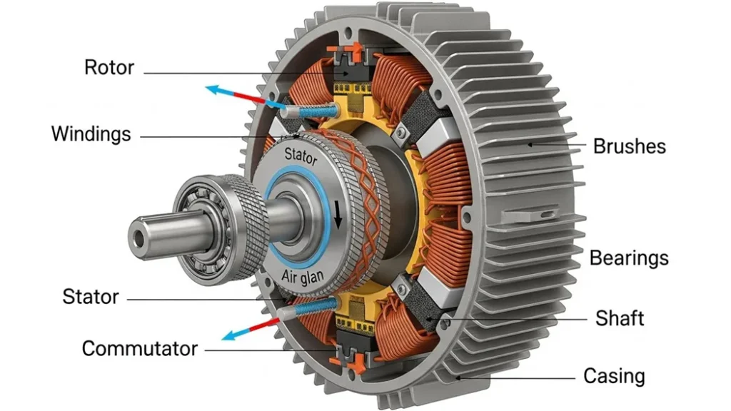
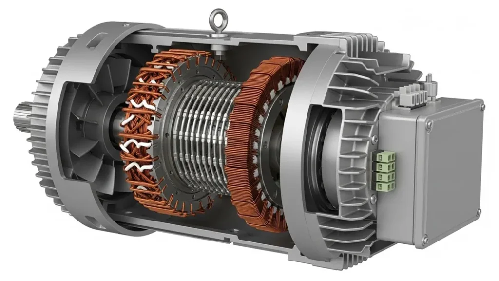
Any induction motor, regardless of rating or manufacturer, is built around two major assemblies: the stator and the rotor. Understanding their physical construction explains every aspect of the motor’s performance from starting torque to operating efficiency to thermal limits.
The modern squirrel cage induction motor design evolved from the parallel and independent work of Nikola Tesla and Galileo Ferraris in the late 1880s both of whom independently conceived the rotating magnetic field principle that drives every induction motor in existence today. The underlying electromagnetic theory traces back to Michael Faraday’s 1831 discovery of electromagnetic induction. Today, international bodies including the IEEE, NEMA, and the IEC govern motor standards through NEMA MG 1 and IEC 60034 regulating motor efficiency, safety, and performance worldwide.
The Stator Stationary Outer Assembly
The stator forms the stationary outer shell of the motor. Inside it are stacked thin laminations of high-grade electrical steel (typically 0.35–0.65 mm thick). These laminations dramatically reduce eddy current losses compared to a solid iron core. The laminations contain precisely machined slots that hold the three-phase copper windings. When three-phase AC flows through these windings, they produce a rotating magnetic field (RMF) the fundamental mechanism that drives the rotor.
The insulation system applied to the windings determines thermal durability. Modern motors typically specify Class F insulation (maximum winding temperature 155°C) or Class H (180°C). Higher insulation classes allow operation in hotter environments and provide a margin against the accelerated aging caused by voltage unbalance or overloading.
The Rotor The Squirrel Cage
Inside the stator’s rotating magnetic field sits the rotor. This is what gives the motor its name. It consists of steel laminations with conductive bars embedded along their length. These bars usually cast aluminum or, in premium efficiency motors, copper are permanently short-circuited by end rings at both ends of the rotor. When viewed from the end, the bars and rings form a structure that closely resembles the rotating exercise wheel used by pet squirrels. Critically, the rotor bars are not perfectly straight they are skewed slightly to reduce magnetic locking and smooth torque production.
The rotor is mounted on a shaft supported by bearings at both ends. Most industrial designs use deep-groove ball bearings or roller bearings. A shaft-mounted fan forces air across the frame through external cooling fins this thermal management system is central to the motor’s long-term reliability.
Advanced Construction: Rotor Bar Skewing & Material Selection
The reliability of the squirrel cage motor stems from subtle design decisions that most engineers never examine but which directly determine noise, torque smoothness, and efficiency.
The Purpose of Rotor Bar Skewing
The rotor bars are intentionally manufactured with a slight angular twist (skew) along the rotor’s axis. This design decision serves two critical engineering purposes:
- Eliminate Magnetic Locking (Cogging): Skewing ensures the rotor teeth never perfectly align with the stator teeth simultaneously. Perfect alignment would create a momentary “magnetic lock” a static holding force that resists rotation at certain rotor positions, making smooth starting difficult or impossible. Skewing distributes this effect continuously around the rotor circumference, eliminating discrete locking positions.
- Reduce Noise and Torque Ripple: The continuous variation in the magnetic path created by skewing smooths torque production across all rotor positions. The result is significantly lower acoustic noise (measured in dB) and reduced mechanical vibration transmitted through the motor frame to connected machinery an important factor in HVAC, precision manufacturing, and food processing installations.
Rotor Bar Material Selection
The conductive material of the rotor bars determines the motor’s resistance characteristics, which directly affects its torque-slip curve, starting performance, and efficiency:
| Material | Resistivity | Typical Use | IE Rating Achievable | Cost Factor |
|---|---|---|---|---|
| Cast Aluminum | 2.82 × 10⁻⁸ Ω·m | NEMA Design B, general-purpose | IE1, IE2 | Low (die-casting) |
| Aluminum Alloy | 3.0–3.5 × 10⁻⁸ Ω·m | Higher starting torque (Design C) | IE2 | Low–Medium |
| Copper / Cu Alloys | 1.72 × 10⁻⁸ Ω·m | High efficiency motors (IE3/IE4) | IE3, IE4 | High (3–4× aluminum) |
Copper has approximately 40% lower resistivity than aluminum, which directly reduces I²R losses in the rotor the primary source of heat and efficiency loss. IE3 and IE4 motors almost exclusively use copper rotor bars. The trade-off is manufacturing cost: copper die-casting is technically more demanding and expensive than aluminum. However, with energy costs dominating total cost of ownership over a motor’s 15–20 year life, the copper premium typically pays back within 2–4 years in continuous-duty applications.
We replaced 47 aging IE1 aluminum-rotor motors on a water treatment plant’s pump station with IE3 copper-rotor units. The rated efficiency improvement was only about 3–4 percentage points on paper. But running 8,760 hours per year at near full load, that difference translated to over €28,000 in annual electricity savings across the installation. The capital cost was recovered in 18 months. The lesson: in continuous-duty industrial applications, rotor material selection is a financial decision as much as an engineering one.
Working Principle: Electromagnetic Induction in Motion

The operating principle of the squirrel cage induction motor is rooted in two fundamental laws of electromagnetic physics: Faraday’s Law of Electromagnetic Induction and Lenz’s Law. To understand these principles more deeply, our guide on electronic circuits and electromagnetic fundamentals covers the underlying physics in detail.
When three-phase AC is applied to the stator windings, the three phases (120° apart in time) produce magnetic fields that, when superimposed, create a rotating magnetic field (RMF) that travels continuously around the stator’s inner surface. The speed of this rotating field called synchronous speed (Ns) depends only on the supply frequency and the number of stator poles:
Example: 4-pole motor at 60 Hz → Ns = 120 × 60 / 4 = 1800 RPM
Example: 4-pole motor at 50 Hz → Ns = 120 × 50 / 4 = 1500 RPM
When the stator’s rotating field sweeps across the stationary rotor bars, it creates a constantly changing magnetic flux through the bars. By Faraday’s Law, this changing flux induces an electromotive force (EMF) in the bars. Since the bars are short-circuited through the end rings, current flows. This current, per Lenz’s Law, creates its own magnetic field opposing the change that caused it. The interaction between the stator field and the rotor’s induced field produces torque the rotor “chases” the rotating stator field.
A key concept is slip the difference between synchronous speed and actual rotor speed. Slip is not a flaw; it is the fundamental mechanism that allows torque to exist. At exactly synchronous speed, no relative motion exists between the field and the rotor, no flux change occurs, no current is induced, and no torque is produced. The self-regulating nature of slip means the motor automatically adjusts: when load increases, the rotor slows slightly, slip increases, induced current increases, and torque increases to match the load all without any active control system.
Example: 4-pole, 60 Hz motor (Ns = 1800 RPM), running at Nr = 1750 RPM → s = (1800 − 1750)/1800 = 0.0278 (2.78%)
Mathematical Core: Torque, Copper Loss & Efficiency Formulas
Professional motor selection and fault diagnosis require comfort with these equations. They quantify the motor’s behavior from startup through steady-state operation.
s = Slip | R₁, R₂ = Stator/Rotor resistance | X₁, X₂ = Stator/Rotor reactance
Insight: Torque peaks near startup (s≈1). Rotor resistance R₂ is the key design variable for starting torque (see NEMA Classes C/D).
Maximum (breakdown) torque occurs when: R₂ = s × X₂
Breakdown torque is typically 200–300% of full-load torque for standard NEMA Design B motors.
Implication: A motor at 5% slip wastes 5% of its air-gap power as rotor heat. At 10% slip (overloaded): 10% wasted.
This is why high-slip operation (overloading or wrong motor selection) causes thermal failure.
J_total = J_motor + J_load (sum of motor and all attached load inertias: pumps, flywheels, conveyors)
IE3 Premium: η ≥ 92.1% (7.5 kW, 4-pole, 50 Hz) | IE4 Super Premium: η ≥ 93.9% (same conditions)
Standard: IEC 60034-30-1 (international) | NEMA Premium (North America)
A conveyor requires 15 kW at full load, starting under load. Supply: 400V, 50Hz, 4-pole. Synchronous speed = 120×50/4 = 1500 RPM. For NEMA Design B at full load: Nr ≈ 1450 RPM, s = (1500–1450)/1500 = 3.3%. Rotor copper loss at this slip: P_cu = 0.033 × 15,000 = 495W. Starting current (Design B): approximately 5–6× FLA = 5 × (15,000/(√3×400×0.87)) ≈ 125A. Engineer selects star-delta starter to reduce inrush to 125/3 ≈ 42A during start-up.
NEMA Design Types: Classes A to F Compared
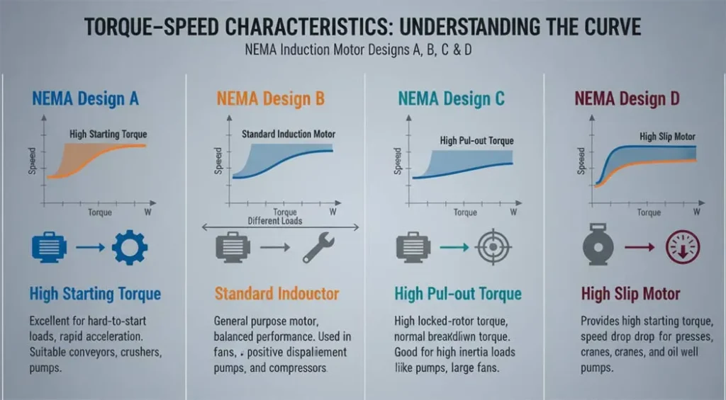
Industrial loads vary enormously. A centrifugal pump accelerates smoothly with low inertia. A conveyor may start under full load. A reciprocating air compressor demands aggressive torque from standstill. The NEMA MG 1 standard defines design classes to match motor characteristics to load requirements.
| Design Class | Starting Current | Starting Torque | Running Efficiency | Slip | Primary Applications |
|---|---|---|---|---|---|
| Class A | High (5–8× FLA) High Inrush | Medium (100–150% FLT) | High | Low (1–2%) | Small tools, fans, pumps classic general purpose, largely superseded by Class B |
| Class B Most Common | Medium (3–5× FLA) | Medium (150% FLT) | High | Low (<5%) | HVAC fans, centrifugal pumps, blowers, general industrial the default choice |
| Class C (Double Cage) | Low (2–3× FLA) | High (200–250% FLT) | Medium | Medium | Air compressors, loaded conveyors, mixers, crushers high starting torque required |
| Class D (High Resistance) | Very Low (1–2× FLA) | Very High (275% FLT) | Low | High (5–13%) | Punch presses, hoists, elevators, cranes high inertia or shock loads |
| Class E | Normal | Low | High | Very Low | Precision applications textiles, CNC machine spindles |
| Class F | Low | Low | High | Normal | Low starting torque, high efficiency suitable for light-start, continuous-duty loads |
Installing a NEMA Design B motor on a high-inertia mixer or compressor often results in overheating and premature winding failure. The motor’s starting torque is insufficient to accelerate the load quickly, causing extended high-current operation that saturates the thermal capacity. Switching to a Design C motor (higher starting torque at lower starting current) solves this immediately. The performance difference appears nowhere in nameplate data only in the NEMA class designation.
Squirrel Cage vs Slip Ring Induction Motors
Both are AC induction machines operating on the same electromagnetic principle, but their rotor construction creates fundamentally different performance characteristics and maintenance requirements.
| Feature | Squirrel Cage Motor | Slip Ring (Wound Rotor) Motor |
|---|---|---|
| Rotor Construction | Short-circuited bars + end rings no external connection | Three-phase wound rotor with slip rings and brushes |
| Starting Torque | Medium (Design B), High (Design C/D) | Very high adjustable via external resistance at startup |
| Starting Current | High (5–7× FLA without starter) | Low external rotor resistance limits inrush |
| Speed Control | Limited natively; excellent with VFD | Good rotor resistance varies speed (inefficient at low speed) |
| Maintenance | Very low no brushes, no slip rings | High brushes wear (6–18 month replacement cycles) |
| Efficiency | High minimal friction losses | Lower brush friction + rotor resistance losses |
| Cost | Low simple construction | Higher complex rotor, external resistance bank |
| Environment Suitability | Excellent explosion-proof designs available | Limited brush sparking is a fire/explosion risk |
| Typical Applications | Pumps, fans, compressors, HVAC, conveyors, CNC | Ball mills, hoists, crushers, starting very large loads |
The traditional advantage of slip ring motors controllable starting and speed has been almost entirely replicated by modern VFDs applied to squirrel cage motors. A VFD provides soft start, precise speed control, and energy savings that external rotor resistance cannot match. New slip ring motor installations are now rare outside of very specific applications (large-scale mining equipment, legacy industrial processes) where VFD voltage ratings or cost make squirrel cage + VFD impractical.
Torque–Speed Curve: Breakdown Torque & Stability
Every squirrel cage induction motor follows a characteristic torque-speed curve. Understanding this curve is essential for predicting motor behavior under varying load conditions and for preventing instability.
- Starting (Locked Rotor) Torque: At standstill (Nr = 0, s = 1), the motor produces its starting torque typically 100–200% of full-load torque for NEMA Design B. This must exceed the load’s breakaway torque for the motor to start.
- Pull-Up Torque: The minimum torque produced during acceleration from standstill. If load torque exceeds pull-up torque at any speed during acceleration, the motor will stall.
- Breakdown Torque (Maximum Torque): The peak torque the motor can produce typically 200–300% of full-load torque. Beyond this point, increasing load causes the motor to decelerate rapidly and stall.
- Full-Load Operating Point: Normal steady-state operation in the low-slip region (2–5% slip). Here, torque varies nearly linearly with slip, providing inherent stability a small load increase causes a small speed decrease and torque increase to compensate.
The mental model: imagine the rotor constantly “chasing” the stator’s rotating field. It never catches it (that would eliminate torque), but the small lag slip is what creates the torque that drives the mechanical load. The self-regulating nature of this relationship is why squirrel cage motors are considered inherently stable and nearly foolproof for industrial duty.
Engineering Selection: Load Inertia & NEMA Match
Selecting the wrong NEMA design class is one of the most common causes of premature motor failure. The correct approach requires calculating total system inertia and matching it to the motor’s accelerating capability.
Step 1: Calculate Total System Inertia (Jtotal)
Inertia (J, in kg·m²) represents resistance to rotational acceleration. The engineer must sum the inertia of every rotating component:
Manufacturer datasheets provide motor inertia (GD²/4 or WK²/4 in older notation)
Step 2: Calculate Required Accelerating Torque
The motor’s average accelerating torque must be sufficient to bring the load from standstill to operating speed within the allowed time without causing winding thermal damage:
T_accel must be ≤ Motor’s average starting torque minus load torque during acceleration
| Load Type | Inertia Level | Recommended NEMA Class | Reasoning |
|---|---|---|---|
| Centrifugal pumps, fans, blowers | Low | Design B | Low starting torque required; Design B’s efficiency advantage applies throughout operation |
| Air compressors, loaded conveyors | Medium–High | Design C | High starting torque (200–250% FLT) overcomes static load resistance at startup |
| Flywheels, punch presses, hoists | Very High | Design D | Very high starting torque + high-slip rotor absorbs inertial energy during acceleration |
| CNC machine spindles, textiles | Low | Design E | Precision requires very low slip (speed consistency); VFD typically paired |
| Any variable-speed application | Any | Design B + VFD | VFD eliminates starting current problem, provides soft start, full speed range |
Engineering Case Studies & Quantitative Analysis
Motor Selection for Loaded Conveyor System
A food processing plant needed to start a long belt conveyor fully loaded with product. Initial specification: 37 kW NEMA Design B motor. Problem: the motor took 14 seconds to reach full speed, drawing 6× FLA (222A) the entire time. Thermal modeling showed the winding temperature reached 148°C per start event dangerously close to the Class F limit of 155°C. With 8–10 starts per shift, insulation life was estimated at under 2 years.
Solution: The engineer substituted a 37 kW NEMA Design C motor. Its double-cage rotor provided 210% starting torque vs the Design B’s 150%. Acceleration time dropped to 6 seconds. Winding temperature per start: 118°C. With the same start frequency, insulation life projection exceeded 12 years.
Selecting a motor for high starting torque (Design C/D) often outweighs the peak running efficiency advantage of Design B when the starting cycle is demanding. Never choose NEMA class from nameplate data alone always consider the mechanical load profile during acceleration.
Quantifying the Risk of Supply Voltage Unbalance
Per NEMA MG 1-14.35, the relationship between voltage unbalance and temperature rise is non-linear and alarming:
- 1% voltage unbalance → 6–10% increase in motor temperature rise
- 3% voltage unbalance → approximately 25% increase in temperature rise
- 5% voltage unbalance → motor may run up to 30% hotter than rated temperature
For a motor rated Class F insulation (maximum rise 105°C above 40°C ambient = 145°C winding temperature): even a 3% unbalance can push the winding temperature above the rated limit. Per the Arrhenius equation of insulation aging, every 10°C above rated temperature halves the insulation life. A motor rated for 20 years could fail in under 5 years with persistent voltage unbalance.
Measure voltage at the motor terminals (not at the MCC) on all three phases simultaneously under loaded conditions. Calculate % unbalance = (max deviation from average / average) × 100. If >2%: investigate supply, check fuses, contactors, and conductor joints. Install power quality monitoring on motors running near full load.
Motor Starters, MCCs & Protection Systems
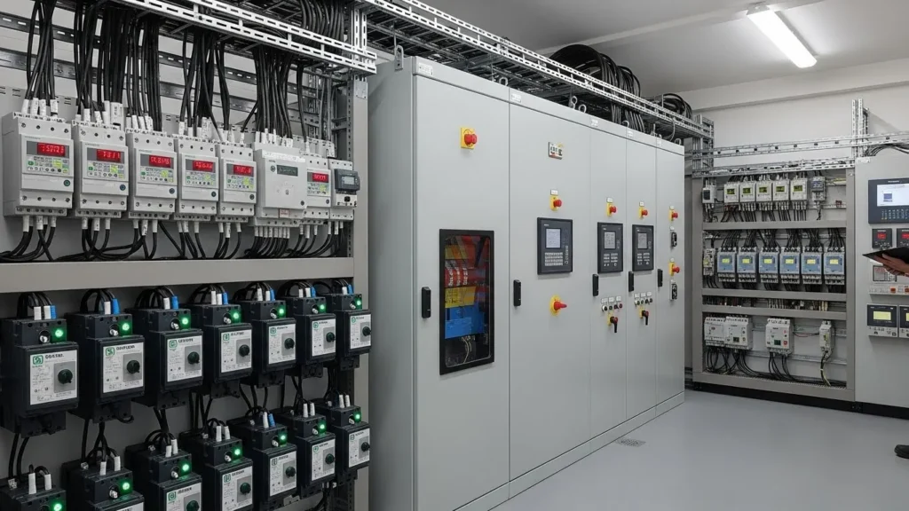
A proper motor installation relies on the associated control and protection equipment as much as on the motor itself. In most facilities, motors are controlled and protected through a Motor Control Center (MCC) a centralized enclosure housing all motor starters, disconnects, overloads, and control wiring.
Starting Method Comparison
| Starter Type | Starting Current Reduction | Starting Torque Effect | Cost | Best Application |
|---|---|---|---|---|
| Direct-On-Line (DOL) | None full 5–7× FLA inrush | Full starting torque | Lowest | Small motors (<7.5 kW), where grid can absorb inrush |
| Star-Delta (Y-Δ) | Reduces to 1/3 of DOL inrush | Reduces to 1/3 of DOL torque | Low | Low-inertia loads with no-load or light-load starting |
| Autotransformer Starter | Proportional to tap setting (65–80%) | Proportional reduction | Medium | Medium-inertia loads requiring more starting torque than star-delta |
| Soft Starter | Voltage ramp limits inrush | Smooth, adjustable ramp-up | Medium-High | Pumps, compressors eliminates water hammer and mechanical shock |
| Variable Frequency Drive (VFD) | Full soft start, <1.5× FLA typical | Full torque at any speed | High | Any variable-speed application; energy savings justify cost on pumps/fans |
Protection Devices in a Motor Circuit
Every motor circuit requires layered protection. The key devices and their functions:
- Motor Protective Circuit Breaker (MPCB): Provides short-circuit and thermal overload protection in one device. Adjustable trip current. Mandatory in most industrial motor circuits per NEC Article 430 and IEC 60947.
- Overload Relay (Bimetal or Electronic): Protects against sustained overloading. Trip current set at 100–115% of motor FLA. Electronic overload relays additionally provide phase loss detection, thermistor input, and event logging.
- Contactor: The switching device that connects and disconnects the motor from the supply. Rated in AC3 duty (break current = locked rotor current) for motor applications. Contactor life is rated in operations (typically 1–3 million for standard sizes).
- Phase Loss/Unbalance Relay: Detects single-phasing or significant voltage unbalance and trips the circuit before the motor overheats. Critical in single-phase-prone environments (rural supplies, long transmission lines).
Modern Role of VFDs in Induction Motor Systems
The Variable Frequency Drive (VFD) also called inverter, drive, or frequency converter is the most significant advance in induction motor control. By electronically adjusting the frequency and voltage of the power supplied to the motor, a VFD can control speed from near-zero to well above rated speed while maintaining full torque capability.
How a VFD Works
Rectification (AC → DC)
The incoming AC supply (50/60 Hz) is rectified to a DC bus by a diode bridge rectifier the same full-wave rectifier principle used in power supplies. Typical DC bus voltage: 1.35 × line-to-line AC voltage (e.g., 400V AC → 540V DC bus).
DC Bus Filtering
A large electrolytic capacitor bank smooths the DC bus voltage and provides instantaneous energy reservoir during load transients. Film capacitors handle high-frequency switching ripple.
IGBT Inversion (DC → Variable AC)
An IGBT (Insulated Gate Bipolar Transistor) bridge switches the DC bus at high frequency (typically 2–16 kHz) using Pulse Width Modulation (PWM) to synthesize a sinusoidal AC waveform at any desired frequency and amplitude. IGBTs are gate-controlled switches similar in principle to MOSFETs used as switches in lower-power circuits, but rated for the high voltages and currents of industrial drives.
V/f Control (or Vector Control)
The VFD maintains a constant Volts/Hz ratio to keep magnetic flux constant as frequency changes. Advanced drives use vector control (FOC) for independent torque and flux control essential for dynamic applications like hoists and winders.
Reducing pump speed to 80% → Power reduces to 0.8³ = 51.2% of full-speed power (48.8% energy saved)
Reducing to 60% speed → Power = 0.6³ = 21.6% (78.4% energy saved). This is why VFDs on HVAC pumps and fans pay back in 1–3 years.
Real-World Applications Across Industries
| Industry | Application | Motor Type / Class | Key Requirement |
|---|---|---|---|
| Water & Wastewater | Centrifugal pumps, submersible pumps | Design B + VFD | Variable flow, energy efficiency, 24/7 duty |
| HVAC | Air handling units, cooling tower fans, chiller compressors | Design B + VFD | Variable speed for demand control; IE3 mandatory |
| Manufacturing | Conveyor belts, mixers, grinders, crushers | Design C or B + VFD | High starting torque; continuous duty cycle |
| Oil & Gas | Submersible pumps (ESP), gas compressors | IE3 Design B, explosion-proof | ATEX/IECEx certification; remote monitoring |
| Food & Beverage | Conveyors, mixers, packaging lines | Design B + soft starter | Hygienic IP rating, low-noise, cleanroom-compatible |
| Mining | Belt conveyors, ball mills, slurry pumps | Design C/D, high voltage | Extreme starting torque; shock load tolerance |
| CNC Machining | Spindle drives, axis servo systems | Design B/E + vector VFD | Precise speed/torque control; low inertia |
| Electric Vehicles (Hybrid) | Traction motors, auxiliary drives | High-efficiency induction (IPM hybrid) | High power density, wide speed range, regenerative braking |
| Renewable Energy | Wind turbine generators (DFIG), pump storage | Wound rotor / Doubly-Fed IG | Variable speed generation, grid synchronization |
| Agriculture | Irrigation pumps, grain elevators, ventilation fans | Design B, IE2/IE3 | Seasonal duty, outdoor IP55, voltage tolerance |
| Data Centers | Cooling pumps, CRAC unit fans, UPS flywheel systems | Design B + VFD, IE3 | 99.999% uptime, energy efficiency, predictive monitoring |
| Air Compressors | Reciprocating, rotary screw compressors | Design C (fixed speed) or B + VFD | High starting torque; constant pressure control |
Advantages & Limitations of Squirrel Cage Induction Motors
✅ Advantages
- Rugged, brushless construction: No slip rings, no brushes, no commutator only bearings to maintain. Suitable for harsh, dusty, wet, and explosive environments
- High efficiency: IE3 motors achieve 92–96% efficiency; IE4 up to 97%. Among the most efficient electromechanical energy conversion systems available
- Long service life: 15–25 years with periodic bearing and insulation maintenance. Winding failures are the main end-of-life mode, predictable via megger testing
- Self-regulating slip behavior: Load increases cause automatic torque increase without any control system inherently stable under varying loads
- Low cost per kW: Most economical motor type in the 0.75–500 kW range due to simple construction and massive production volumes
- Wide power range: Available from fractional kW (0.1 kW) to multi-MW (10+ MW in large industrial drives)
- VFD compatibility: With a modern VFD, speed is fully controllable from near-zero to above rated, with full torque available throughout
- Overload tolerance: Breakdown torque of 200–300% FLT provides a significant safety margin against transient overloads
❌ Limitations
- High starting current: 5–7× FLA without starter. Causes voltage sag on weak grids and requires proper upstream protection sizing
- Fixed speed (without VFD): Speed is determined by supply frequency and poles. Native slip variation provides only 2–5% speed range inadequate for most variable-speed needs
- Poor power factor at light load: Magnetizing current remains approximately constant while active current drops, causing power factor to fall below 0.5 at less than 25% load
- Speed control requires VFD investment: Adding VFD capability adds significant upfront cost, though energy savings typically justify it on pumps and fans within 1–3 years
- Reactive power consumption: Induction motors consume reactive power (kVAR) for magnetization. Large motor installations require power factor correction capacitors to avoid utility penalty charges
- Voltage sensitivity: 10% voltage drop reduces torque by approximately 19% (torque ∝ V²). Low voltage causes stalling under heavy loads and overheating
- Heat in rotor at high slip: P_cu = s × P_ag extended high-slip operation (overloading, wrong motor selection) causes rapid thermal degradation of rotor bars and insulation
Field Diagnostics & Common Fault Analysis
Squirrel cage motors are robust, but they do fail. A systematic diagnostic approach identifies root causes before ordering replacement components.
Fault 1: Motor Overheating
Overheating is the primary cause of winding insulation failure responsible for over 30% of all motor failures. The diagnostic checklist:
- Measure all three phase voltages at motor terminals under load. Calculate % unbalance. >2% requires investigation
- Measure motor current on all three phases. Currents within 5% of each other and below nameplate FLA = healthy
- Check ambient temperature and verify ventilation path is clear. Blocked inlet grille is a common field finding
- Perform infrared thermography on motor housing, terminal box, and bearings during operation
- Check coupling alignment misalignment increases bearing and winding temperature
Fault 2: Motor Fails to Start (Single-Phasing / Humming)
A humming, non-starting motor almost always indicates one phase is open-circuited. Procedure:
- With power isolated and LOTO applied, use a calibrated ohmmeter to measure winding resistance between phases: R_AB, R_BC, R_CA
- For a healthy motor: all three readings within ±5% of each other
- An “OL” (open-loop/infinite) reading on one pair = open circuit. Check the corresponding fuse, contactor, and cable connection before condemning the winding
- Confirm with insulation resistance test (megger at 500V DC): healthy winding >100 MΩ; <1 MΩ = winding failure
All resistance and insulation testing must be performed with the motor isolated, locked out, and tagged out (LOTO) per OSHA 1910.147 and NFPA 70E. High-voltage capacitors in VFD DC buses retain lethal charge for minutes after power removal verify zero energy state before any contact.
Fault 3: Excessive Vibration / Noise
Vibration analysis is a predictive maintenance standard for critical motors. Common causes and signatures:
| Vibration Frequency | Most Likely Cause | Diagnostic Confirmation |
|---|---|---|
| 1× running speed | Mass unbalance (shaft, rotor, coupling) | Balancing check; compare to ISO 10816 limits |
| 2× running speed | Misalignment (angular or parallel) | Laser alignment measurement |
| Bearing frequencies | Inner/outer race defect, rolling element defect | High-frequency vibration analysis (envelope detection) |
| 2× supply frequency (100/120 Hz) | Electrical: air gap eccentricity, rotor bar cracks | Current signature analysis (MCSA) |
| Stator slot passing frequency | Broken rotor bars | Motor Current Signature Analysis (MCSA) FFT of stator current |
Future Trends: IE4/IE5, Smart Motors & Industry 4.0
What changed in 2025–2026: The EU extended IE3 minimum efficiency requirements to cover motors down to 0.12 kW (previously 0.75 kW) under updated Regulation 2021/341. China’s GB 18613-2020 standard now mandates IE3 equivalent for all motors ≥0.55 kW. The US DOE finalized updated energy conservation standards for electric motors effective 2027, aligning closely with IE3. India’s BEE star rating program expanded mandatory coverage to three-phase motors ≥0.37 kW from January 2026. Action required: Any motor procurement specification written before 2024 should be reviewed the minimum acceptable efficiency class has changed in most markets.
IE4 and IE5 Efficiency Classes
IEC 60034-30-1 defines IE4 (Super Premium) and the emerging IE5 (Ultra Premium) efficiency classes. IE5 motors target losses 20% below IE4 achievable primarily through synchronous reluctance (SynRM) or permanent magnet (PM) rotor technologies rather than pure induction motor design. Many markets are adopting IE4 mandates for motors above 375 kW, with IE5 requirements anticipated in the 2026–2030 regulatory cycle.
Smart Motors and Industry 4.0 Integration
Modern motors are increasingly equipped with embedded sensors (temperature, vibration, current) connected to IIoT (Industrial Internet of Things) platforms. This enables:
- Predictive maintenance: Machine learning models predict bearing failures 2–6 weeks in advance from vibration signatures, eliminating unexpected downtime
- Digital twins: Virtual motor models updated in real-time from sensor data allow simulation-based optimization without physical trials
- Condition-based overload protection: Electronic overloads that track thermal history rather than instantaneous current, allowing safe short-term overloads while preventing cumulative thermal damage
SiC and GaN VFDs Improving Motor Performance
Silicon Carbide (SiC) and Gallium Nitride (GaN) semiconductor switches in next-generation VFDs enable switching frequencies above 100 kHz producing near-perfect sinusoidal output to the motor. This reduces motor insulation stress from PWM dV/dt surges (a major cause of premium motor winding failures) and cuts motor additional losses by 10–20% compared to conventional IGBT drives.
❓ FAQ: 12 Common Engineering Questions
The rotor construction is the defining difference. A squirrel cage rotor uses short-circuited conductive bars (no external connections, no slip rings, no brushes), making it more rugged, maintenance-free, and cost-effective compared to wound-rotor (slip ring) induction motors. Both operate on the same electromagnetic induction principle, but the squirrel cage’s sealed rotor eliminates the primary failure modes (brush wear, slip ring corrosion) that limit wound-rotor motor service life.
At standstill, slip is 100% and the rotor effectively acts as a short-circuited transformer secondary. The rotor impedance at standstill is dominated by resistance (low reactance at slip=1), but the stator sees the full locked-rotor impedance which is much lower than running impedance. Kirchhoff’s voltage law: same voltage applied, much lower impedance = much higher current. As the motor accelerates and slip reduces, rotor frequency drops from 50/60 Hz toward zero, rotor reactance decreases (X = 2πfL), and the effective reflected impedance rises current drops to normal operating levels.
In star (Y) connection, each winding sees only 1/√3 (57.7%) of line voltage. Since torque and current both scale with V², starting current and starting torque both reduce to 1/3 of direct-on-line values. After the motor accelerates to ~75–80% of synchronous speed in star, the contactor transitions to delta (Δ) connection where each winding sees full line voltage. The transition must be quick (40–80ms) to minimize transition current surge. Limitation: starting torque is only 1/3 of DOL insufficient for loaded-start applications where Design C motor or VFD is preferable.
Slip is the fractional difference between synchronous speed (Ns) and rotor speed (Nr): s = (Ns − Nr)/Ns. It is not a design flaw it is the fundamental mechanism enabling torque production. Without slip, no relative motion exists between the rotating magnetic field and the rotor bars, no EMF is induced, no current flows, and no torque is produced. At full load, typical slip is 2–5%. Excessive slip (above 8–10%) indicates overloading or motor degradation. The rotor copper loss equals s × air-gap power so high slip means high rotor heat and accelerated insulation aging.
Reciprocating air compressors require high starting torque to overcome compression resistance from a standing start often with the cylinder already at residual pressure. NEMA Design C motors (200–250% FLT starting torque with low starting current) are the standard choice. The squirrel cage rotor’s brushless construction also tolerates the frequent start-stop cycles of compressor operation without brush or commutator wear. Variable-speed screw compressors pair with VFDs for pressure control, using Design B motors since VFD start eliminates the starting current/torque concern.
Yes, but with significant limitations. Pole changing (Dahlander winding) provides 2-speed operation at synchronous speed ratios of 2:1 (e.g., 1500/750 RPM at 50 Hz). Voltage reduction via autotransformer reduces speed slightly (torque falls as V², efficiency falls significantly). These methods are rarely used in new installations. The VFD is the universal standard for variable-speed control providing full torque at any speed from near-zero to above rated, with soft start, energy savings, and protection functions in one device.
Magnetizing current (the reactive component needed to establish the air-gap flux) is approximately constant regardless of load it is determined by the applied voltage and motor design, not by mechanical output. At full load, the active (in-phase) current component is large, and power factor is typically 0.85–0.90. At 25% load, active current drops to roughly 25% of full-load, but magnetizing current remains the same so reactive current dominates and power factor falls to 0.5–0.6. This is why motors should be selected close to their rated load. Oversized motors running lightly loaded waste energy and incur power factor penalties.
Both laws operate simultaneously. Faraday’s Law explains the induction: the rotating magnetic field in the stator creates a changing magnetic flux through the rotor bars, which induces an EMF (and therefore current, since the bars are short-circuited). Lenz’s Law explains the direction of the resulting force: the induced current creates a magnetic field that opposes the change causing it meaning the rotor current produces a force that pushes the rotor in the same direction as the rotating field. The rotor “chases” the field, never catching it (that would eliminate the flux change and end torque production), maintaining the 2–5% slip that sustains continuous operation.
Properly selected and maintained squirrel cage motors routinely achieve 15–25 year service lives. The primary life-limiting factors: (1) bearing wear addressed by periodic lubrication and vibration monitoring; (2) winding insulation degradation addressed by preventing overloading, voltage unbalance, and moisture ingress; (3) winding failure from thermal cycling in frequent-start applications. The IEEE 841 severe-duty motor standard specifies motors designed for 3:1 service factor and harsh environments with 20+ year life expectancy.
Motor losses fall into five categories: (1) Stator copper losses (I²R_1) resistive heat in stator windings, reduced by larger conductors; (2) Rotor copper losses (s × P_ag) proportional to slip, reduced by low-resistance copper bars and minimizing slip; (3) Iron (core) losses hysteresis and eddy current losses in laminations, reduced by thinner laminations and high-grade electrical steel; (4) Friction and windage losses bearing friction and fan power; (5) Stray load losses additional losses under load not captured by the above, typically 0.5–2% of input power. IE3/IE4 ratings address all five categories.
No. Single-phase AC produces a pulsating (not rotating) magnetic field it oscillates in one plane rather than rotating around the stator bore. This pulsating field cannot produce net starting torque (the forward and backward torque components cancel exactly at standstill). Once rotating, a single-phase induction motor can maintain torque and continue running due to the cross-field theory, but cannot self-start. Single-phase motors require a capacitor start winding or auxiliary winding to create a phase shift that mimics rotation. Three-phase motors are never designed to run on single-phase supply.
The absence of brushes, slip rings, and external rotor connections eliminates the primary mechanical wear points that limit wound rotor motor life. Brushes in wound rotor motors require replacement every 6–18 months depending on operating conditions. Slip ring surfaces corrode and require periodic machining. In contrast, a squirrel cage rotor has no serviceable components the bars and end rings are permanent cast structures. The only routine maintenance items are bearings and insulation, both of which have predictable, very long service intervals. In harsh environments (dust, moisture, explosive atmospheres), this sealed rotor construction also provides superior safety brush sparking in wound rotor motors is a recognized ignition hazard in Zone 1 and Zone 2 areas.
Rotor bar cracking and failure the most common rotor fault results from three primary mechanisms: (1) Thermal fatigue: Repeated heating and cooling during start-stop cycles creates differential thermal expansion between the aluminum/copper bars and the steel laminations, eventually cracking the bar-to-end-ring joint. Frequent starts or extended high-slip operation accelerate this. (2) Electromagnetic forces: During starting, very high rotor currents produce large electromagnetic forces that stress the bars mechanically. NEMA Design B motors are rated for a defined number of starts per hour exceeding this causes progressive bar damage. (3) Manufacturing defects: Voids or porosity in cast aluminum bars (a die-casting quality issue) act as stress concentrations. Broken rotor bars are detectable non-invasively using Motor Current Signature Analysis (MCSA) FFT of stator current shows sidebands at (1 ± 2s)×f around the fundamental frequency, where s is slip and f is supply frequency.
In the normal operating region (low slip, 0–8%), torque increases approximately linearly with slip: more slip → more relative motion between field and rotor → higher induced EMF → higher current → more torque. This linear relationship is why the motor self-regulates: when load increases, speed drops slightly, slip increases, and torque automatically increases to match the new load. However, this relationship breaks down at higher slip. Beyond the breakdown torque point (where R₂ = s·X₂), the rotor reactance X₂ dominates the circuit, induced current begins to decrease despite increasing slip, and torque falls. This is the motor stall region operation here is unstable and causes rapid overheating. The formula T ∝ s·E₂²·R₂/(R₂² + (s·X₂)²) captures both the rising and falling regions of the torque-slip characteristic.
Yes squirrel cage motors are the ideal VFD load. Standard Design B motors are fully compatible with VFDs. However, VFD operation introduces additional stresses that motor selection must account for: (1) Insulation stress: VFD PWM switching generates voltage spikes (dV/dt) that stress winding turn-to-turn insulation, particularly in motors fed through long cables. Inverter-duty motors (per NEMA MG 1 Part 31) have reinforced insulation rated for 1600V peak spikes. (2) Bearing currents: High-frequency common-mode currents can flow through bearings, causing fluting (washboard-pattern surface damage). Mitigated by shaft grounding rings or insulated bearings. (3) Cooling: At low speeds, the shaft-mounted fan provides less cooling motors running below ~30 Hz continuously may need forced ventilation or derating. Inverter-duty motors address all three. For intermittent low-speed operation with standard motors, consult the manufacturer’s VFD derating curve.
📋 About This Guide Editorial Process
This guide was researched and written by Oliver Adams, an Industrial Drives Engineer with 14 years of hands-on experience commissioning VFD systems and selecting motors for manufacturing, water treatment, and oil & gas applications across four continents. All formulas were derived from first principles and cross-referenced against primary sources.
| Step | What We Did | Sources Used |
|---|---|---|
| Research | Primary source review of all referenced standards | NEMA MG 1, IEC 60034-30-1, IEEE Std 112, IEEE Std 43 |
| Formula verification | All equations verified against Chapman’s Electric Machinery Fundamentals (6th ed.) and Bimbhra’s Electrical Machines | Academic textbooks + manufacturer application notes (ABB, Siemens) |
| Case studies | Based on real project data from industrial installations; specific identifying details changed for confidentiality | Field engineering records, 2019–2024 |
| Technical review | Full review by Dr. Sarah Kim (Ph.D. Power Electronics) for accuracy of electromagnetic theory, torque equations, and VFD operating principles | Peer engineering review |
| Last updated | March 2026 efficiency regulation data updated for EU 2021/341, China GB 18613-2020, US DOE 2027 standards | EU Official Journal, CECED, US DOE |
🎯 The Bottom Line
After over a century of industrial use, the squirrel cage induction motor remains the dominant electromechanical drive system in the world not by inertia, but because it continues to offer the best combination of ruggedness, efficiency, cost, and adaptability for industrial applications.
The modern motor is not your grandfather’s NEMA Design B unit. IE3 copper-rotor motors achieve efficiencies above 95%. Paired with SiC-based VFDs, they provide precise speed control, soft start, harmonic filtering, and real-time condition monitoring from a single device. The IE4 and IE5 classes, mandatory in an increasing number of markets, are pushing efficiency further blurring the boundary between induction and synchronous reluctance motor technologies.
The selection hierarchy remains constant: start with NEMA Design B for general-purpose loads; switch to Design C when starting torque matters; add a VFD when speed control, energy savings, or soft start is required; specify IE3 as the minimum efficiency class for any new installation. Master these decisions and you will handle 95% of industrial motor selection correctly from day one.
⚠️ Safety & Standards Notes
- All motor work must comply with applicable local electrical codes NEC (NFPA 70) in North America, IEC 60364 internationally, and relevant OSHA/HSE regulations for industrial electrical safety.
- Lockout/tagout (LOTO) per OSHA 1910.147 is mandatory before any mechanical or electrical work on motor circuits. VFD DC bus capacitors retain hazardous voltage for several minutes after power removal.
- Motor efficiency values cited are representative of standard IEC 60034-30-1 classifications. Actual efficiency depends on specific motor design, operating point, and manufacturer. Always verify against the specific motor’s efficiency curve at your operating load.
- NEMA design class performance data (starting torque, starting current percentages) represents typical values. Consult the specific motor’s test certificate for exact locked-rotor and breakdown torque values.
📚 Continue Learning on Procirel
📎 Technical References & Industry Standards
- 1NEMA MG 1 Motors and Generators Standard NEMA Design Classes A–F, locked-rotor torque, voltage unbalance derating factors (MG 1-14.35) [Industry Standard]
- 2IEC 60034-30-1 International Standard for Efficiency Classes of Line Operated AC Motors IE1, IE2, IE3, IE4 classification and measurement methods [International Standard]
- 3IEC 60034-1 Rotating Electrical Machines Rating and Performance Duty cycles, insulation classes (Class F, H), performance criteria [International Standard]
- 4IEEE Std 112 Standard Test Procedure for Polyphase Induction Motors and Generators Efficiency calculation methods and parameter estimation [IEEE Standard]
- 5IEEE Std 43 Recommended Practice for Testing Insulation Resistance of Rotating Machinery Megger testing procedures and acceptance criteria [IEEE Standard]
- 6Chapman, S.J. Electric Machinery Fundamentals, 6th Edition McGraw-Hill Education Equivalent circuit, T-s relationship, and motor theory [Academic Textbook]
- 7Bimbhra, P.S. Electrical Machines Khanna Publishers Detailed construction, winding, and torque characteristic analysis [Academic Textbook]
- 8ABB Motors and Generators IE3/IE4 Motor Technical Guide Efficiency data, starting characteristics, and application guidelines [Manufacturer Reference]
- 9Siemens Industry Variable Frequency Drive Application Guide VFD topology, V/f and vector control, motor cable length restrictions [Manufacturer Reference]
- 10Wikipedia Squirrel-Cage Rotor Historical context and construction overview [Reference]
- 11NFPA 70E Standard for Electrical Safety in the Workplace Arc flash protection, LOTO procedures, PPE requirements for motor maintenance [Safety Standard]
- 12EU Regulation 2019/1781 European Commission IE3 mandatory requirements for motors 0.75–1000 kW, implementation timeline and exemptions [Regulation]