Key takeaways for Electron Devices
Whether you’re a student or a hobbyist, understanding electronic devices and circuits doesn’t have to be complicated. This guide breaks down everything from basic components like resistors and transistors to complex systems like mixed-signal and power circuits. We don’t just talk theory; we show you how formulas like the RC time constant and ripple factor actually dictate circuit behavior. You’ll walk through a real-world design flow starting from a schematic, moving to simulation, and finishing with a high-quality PCB layout. Plus, we highlight critical safety standards (like IEEE and AEC-Q) used in medical and automotive tech to ensure your projects are professional and reliable. Use our Table of Contents to jump straight to the section you need
Introduction to Electron Devices and Circuits
Electron devices and circuits constitute the fundamental infrastructure of all modern electronics, relying on the controlled manipulation of charge carriers within materials ranging from vacuum tubes to advanced semiconductor junctions. This comprehensive guide provides a rigorous, foundational-to-advanced overview of the field, moving beyond simple component definitions. We will explore the mathematical principles of circuit analysis (including transient response and filtering) and delve into the operational theory of active devices, such as Bipolar Junction Transistors (BJT) and Metal-Oxide-Semiconductor Field-Effect Transistors (MOSFET). Understanding these concepts is essential for designing systems, from precision analog amplifiers and digital logic gates to complex integrated circuits (ICs) that drive Very-Large-Scale Integration (VLSI) and modern Edge Computing applications.
What Are Electron Devices?

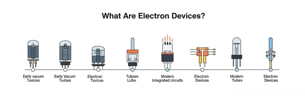
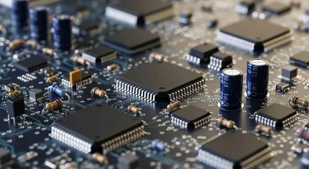
Electronic devices, including electronic circuit board components, are instruments that manipulate the flow of electrons to perform specific tasks. These devices range from simple components like resistors, which limit current, to complex systems like microprocessors that process billions of instructions per second. At their core, electron devices rely on the principles of electricity and electron behavior, often governed by fundamental laws like Ohm’s Law ( V=IR ), which relates voltage, current, and resistance.
Consider a smartphone: it’s a marvel of electron devices working in harmony. Inside, you’ll find transistors controlling signals, capacitors storing energy, and integrated circuits orchestrating complex operations. These devices aren’t limited to consumer gadgets; they’re critical in medical devices like pacemakers, industrial automation systems, and even satellite communication. Electron devices can be as straightforward as a single resistor in a circuit or as intricate as a system-on-chip powering artificial intelligence.
| Electron Device Examples | Description |
|---|---|
| Resistor | Limits current flow in a circuit |
| Transistor | Amplifies or switches electronic signals |
| Smartphone | Complex system integrating multiple electron devices |
Types of Electron Devices
Electron devices come in various forms, each with distinct roles in circuits. Let’s break them down into four key categories: passive devices, active devices, semiconductor devices, and electromechanical devices.
Passive Devices

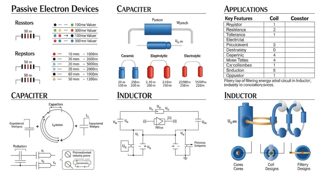
Passive devices don’t require an external power source to function and cannot amplify signals. They include resistors, capacitors, and inductors. A resistor, for instance, restricts current flow, ensuring circuits operate within safe limits. Ohm’s Law (V=IR ) governs resistors, where voltage (V) equals current (I) multiplied by resistance (R). For example, in an LED circuit, a resistor prevents excessive current from damaging the LED.
Capacitors store electrical energy and release it when needed, making them vital in timing circuits. In a simple RC (resistor-capacitor) circuit, the time constant (τ=RC ) determines how quickly a capacitor charges or discharges. Inductors, on the other hand, store energy in magnetic fields and are used in filters or transformers. These devices are the building blocks of circuits, providing stability and control.
Comparison of Electron Devices
| Category | Examples | Role |
|---|---|---|
| Passive | Resistor, Capacitor | Control current, store energy |
| Active | Transistor, Diode | Amplify or switch signals |
| Semiconductor | Diode, Transistor | Precise control, miniaturization |
| Electromechanical | Relay, Motor | Combine electrical and mechanical functions |
Comparison of Electronic Circuits
| Type | Signal | Example | Use Case |
|---|---|---|---|
| Analog | Continuous | Audio amplifier | Precise signal manipulation |
| Digital | Discrete (0/1) | Microprocessor | Computing, logic operations |
| Mixed-Signal | Both | ADC in IoT | Sensor interfacing |
| Power | Energy | Voltage regulator | Stable power delivery |
Quantitative Principles: Energy Storage and Transient Response
Passive devices define the energy dynamics and time-dependent behavior (transient response) of a circuit. Mastering these formulas is essential for filter and timing circuit design.
1. Capacitor Charge and Discharge (RC Circuits)
The voltage across a capacitor (vc) during charging (from zero) or discharging follows an exponential curve governed by the Time Constant (τ), where τ=RC
.
vc (t) = Vsource ( 1 − e − tτ )
The capacitor reaches approximately 63.2% of its final voltage after one time constant (τ).
This principle is the basis for oscillators, timers, and power supply ripple reduction.
2. Inductor Energy Storage
Inductors store energy in a magnetic field, resisting changes in current flow. The energy stored (E) is a function of the inductance (L) and the current (I):
E=12L I2
This storage capability makes inductors critical for switching mode power supplies (SMPS) and RF filtering circuits. The behavior of semiconductor devices is strictly defined by non-linear physical equations, which are fundamental to electronic circuit design.
1. The Shockley Diode Equation
The diode’s exponential current-voltage (I–V) relationship under forward bias is modeled by the Shockley Diode Equation. This formula is critical for modeling rectifiers, clippers, and logic gates:
ID=IS (eV DnVT−1 )
Where IS is the reverse saturation current, VT is the thermal voltage (~26 mV at 25°C), and n is the ideality factor. This non-linear behavior is what enables rectification.
2. Bipolar Junction Transistor (BJT) Current Relationship
For a BJT operating in the Active Region (used for linear amplification), the Collector Current (IC) is directly proportional to the Base Current (IB) by the DC Current Gain (β):
IC=β IB
Selecting the appropriate β value is the first step in designing any single-stage transistor amplifier.
Active Devices
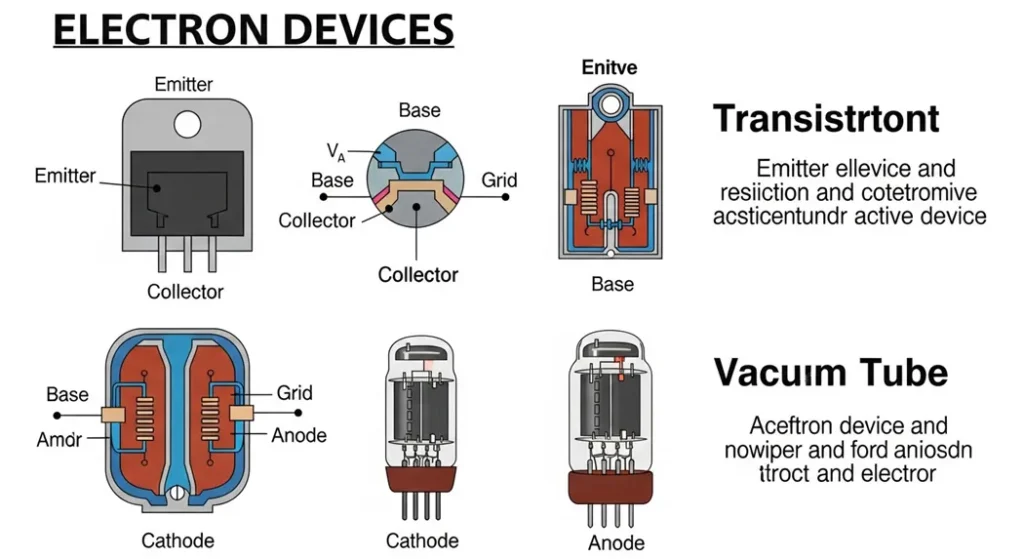
Active devices, like BJT transistors and diodes, require external power to control or amplify signals. BJT NPN transistors and PNP transistors, often called the workhorses of electronics, can act as switches or amplifiers. In a computer, transistors form the logic gates that process binary data. Diodes allow current to flow in one direction, protecting circuits or rectifying AC to DC. Electronic ICs combine thousands or millions of transistors and diodes into a single chip, powering everything from calculators to supercomputers.
BJT Amplification and Operational Regions
The Bipolar Junction Transistor (BJT) is the fundamental active device. Its primary function amplification is quantified by the relationship between its base and collector currents.
Current Gain (β)
The common-emitter DC Current Gain (β or hFE) defines the transistor’s ability to amplify a small base current (IB) into a much larger collector current (IC):
β =IC IB
Typical β values range from 50to 300. This metric is foundational for designing linear amplifiers (analog circuits).
Transistor Operating Regions
A BJT operates in three distinct modes, determining its circuit role:
- Active Region: The proportional amplification region. Used exclusively for Analog Circuits (e.g., audio amplifiers).
- Saturation Region: The transistor acts as a closed switch (fully “ON”), allowing maximum current flow. Used for Digital Logic (Logic 1).
- Cutoff Region: The transistor acts as an open switch (fully “OFF”), blocking current flow. Used for Digital Logic (Logic 0).
Semiconductor Devices
Semiconductors, typically made of silicon, bridge the gap between conductors and insulators. Diodes and transistors are prime examples. A diode’s ability to conduct current in one direction makes it essential in power supplies, while transistors amplify signals in audio systems or switch signals in digital circuits. Advances in semiconductor technology, such as smaller transistors in 2025’s 3nm chips, have driven the miniaturization of devices, enabling powerful yet compact electronics.
Case Study: The Billion-Transistor Wonder in Your Pocket
Ever wondered how your smartphone handles high-end gaming, crystal-clear video calls, and instant apps all at once? The secret lies in billions of microscopic transistors packed into a single chip. These tiny switches act as the “brain cells” of your phone, working tirelessly to amplify data and perform lightning-fast logic operations. Every time you snap a photo or send a message, billions of these components are switching on and off in perfect harmony to make it happen. It’s not just a circuit; it’s a masterpiece of engineering that fits in the palm of your hand.
Electromechanical Devices
Electromechanical devices, like relays circuits and motors, combine electrical and mechanical functions. A relay, for instance, uses an electromagnetic coil to open or close a circuit, commonly found in automotive systems to control high-power devices like headlights. Motors convert electrical energy into motion, driving everything from electric vehicles to industrial machinery. These devices showcase the versatility of electron devices in bridging electrical and physical systems.
| Device Type | Key Examples | Role in Circuits |
|---|---|---|
| Passive | Resistor, Capacitor | Control current, store energy |
| Active | Transistor, Diode | Amplify or switch signals |
| Semiconductor | Diode, Transistor | Enable precise control |
| Electromechanical | Relay, Motor | Combine electrical and mechanical functions |
What Are Electronic Circuits?
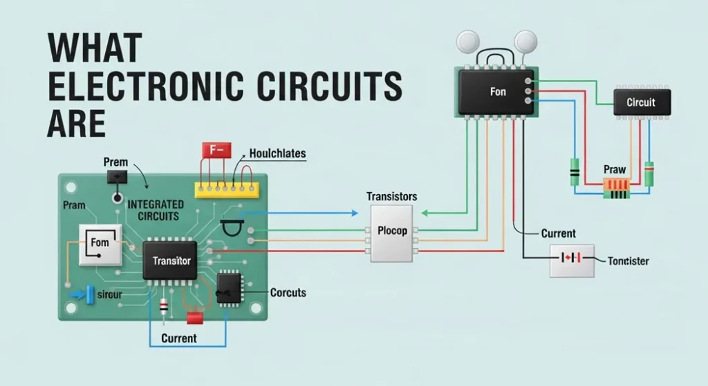
An electronic circuit board is a closed-loop system that allows electrons to flow, performing specific tasks. Think of a circuit as a network of interconnected electron devices working together. A simple circuit, like a flashlight, consists of a battery, switch, and bulb. When the switch closes, current flows, lighting the bulb. In contrast, a computer’s motherboard is a complex circuit with millions of components coordinating to process data.
Circuits are designed to achieve specific outcomes, whether it’s amplifying a signal, processing data, or powering a device. They rely on the interplay of components like resistors, capacitors, and transistors, each contributing to the circuit’s functionality. Understanding circuits is key to mastering electronics, as they form the foundation of every electronic device.
Types of Electronic Circuits
Electronic circuits vary in complexity and purpose. Let’s explore the main types: analog, digital, mixed-signal, and power circuits.
Analog Circuits
Analog in electronics involves circuits that handle continuous signals, such as sound waves in an amplifier electronic circuit. These circuits process signals that vary smoothly over time, like the voltage in a microphone. A classic example is an amplifier electronic circuit, such as an operational amplifier (op-amp) circuit, used in audio equipment to boost weak signals. These circuits, often incorporating a quartz crystal oscillator are critical in applications requiring precise signal manipulation, such as in medical imaging devices.
Case Study: How Op-Amps Save Lives in Healthcare
Think about the last time you saw an ultrasound or an MRI scan. The signals coming from the human body are incredibly faint often too weak for a computer to “see.” This is where the Operational Amplifier (Op-Amp) steps in as a silent hero. In medical imaging, Op-Amps act like a powerful magnifying glass for electricity. They take those tiny, whispers of analog signals and amplify them with extreme precision, turning noise into a clear, high-definition image of a beating heart or a developing baby. Without the accuracy of these circuits, modern diagnostics wouldn’t be possible. It’s a perfect example of how “analog” precision meets “human” needs in healthcare electronics.
Operational Amplifiers (Op-Amps) and Bandwidth Analysis
Operational Amplifiers are the most versatile building blocks in analog design. Their performance is defined by two critical metrics: Gain and Bandwidth.
Closed-Loop Gain and GBWP
In a common Non-Inverting Amplifier configuration, the Closed-Loop Voltage Gain (ACL) is:
ACL = 1 +Rf Rin
The Gain-Bandwidth Product (GBWP) is the constant that defines the maximum frequency (fmax) an Op-Amp can handle at a given gain:
fmax = GBWP / ACL. This trade-off is critical when designing high-speed instrumentation or audio systems.
Troubleshooting: Amplifier Distortion
Common failure modes in power amplifiers include Clipping and Slew Rate Limiting:
- Clipping: Occurs when the input signal demands an output voltage greater than the supply voltage limits. Troubleshooting: Check supply rails or reduce input gain.
- Slew Rate Limiting: Occurs when the input signal’s rate of change (frequency) is faster than the Op-Amp can physically respond to. Troubleshooting: Requires choosing an Op-Amp with a higher Slew Rate (measured in
V/μs) or reducing the maximum frequency of the signal.
Digital Circuits
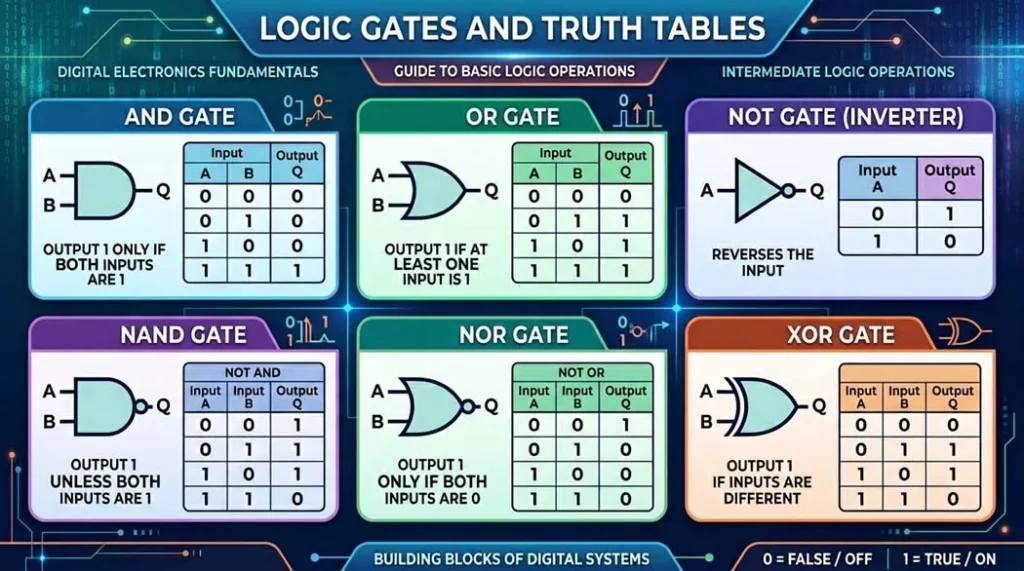
Digital circuits work with discrete signals zeros and ones forming the basis of modern computing. Logic gates, built from transistors, perform operations like AND, OR, and NOT, enabling microprocessors to execute complex tasks. For instance, a digital circuit in a smartwatch processes user inputs to display notifications. As of 2025, digital circuits are increasingly integrated with AI, enabling smarter devices.
Mixed-Signal Circuits
Mixed-signal circuits combine analog and digital elements. Analog-to-digital converters (ADCs) are a prime example, converting continuous signals (like temperature readings) into digital data for processing. These circuits are essential in smartphones, where they bridge the analog world (e.g., touch inputs) with digital processing. Mixed-signal ICs are increasingly vital in IoT devices, enabling seamless data conversion.
Case Study: IoT—The Bridge Between Nature and Digital Intelligence
How does your smart thermostat know it getting too cold or your fitness tracker detect a single step? The physical world temperature motion,and sound is purely analog but the internet is purely digital. The magic happens within Mixed-Signal ICs using an Analog-to-Digital Converter (ADC). Think of the ADC as a master translator: it takes the “feel” of the physical world and converts it into 0s and 1s that your phone can understand. This invisible translation is what powers our smart homes, wearable health monitors, and even industrial robots, making our entire environment more responsive to our needs.
Power Circuits
Power circuits, often using a power management integrated circuit, manage energy delivery, ensuring devices receive stable voltage and current. Voltage regulators, for example, maintain consistent power in a laptop, preventing damage from fluctuations. Power circuits, often incorporating battery circuits, are critical in renewable energy systems, like solar inverters, which convert DC to AC for household use. Efficient power management is a focus in 2025, with advancements in low-power ICs for wearable devices.
| Circuit Type | Signal Type | Example Application |
|---|---|---|
| Analog | Continuous | Audio amplifier |
| Digital | Discrete | Microprocessor |
| Mixed-Signal | Both | ADC in IoT devices |
| Power | Energy management | Voltage regulator |
Case Study: Full-Wave Rectification and Ripple Factor
Diodes are essential in power circuits to convert AC input into a pulsating DC output—a process called rectification. The Full-Wave Bridge Rectifier is the standard configuration for maximizing power efficiency.
Output Quality Metric: Ripple Factor (γ)
The output of a rectifier is not pure DC; it contains AC noise known as ripple. The Ripple Factor (γ) quantifies the quality of the DC output after filtering, with a lower value indicating a cleaner signal:
In an unfiltered full-wave rectifier, γ ≈ 0.482. The addition of a large reservoir capacitor after the bridge circuit dramatically reduces this value (typically below 0.05), ensuring stable power delivery to downstream components.
Key Components in Electronic Circuits
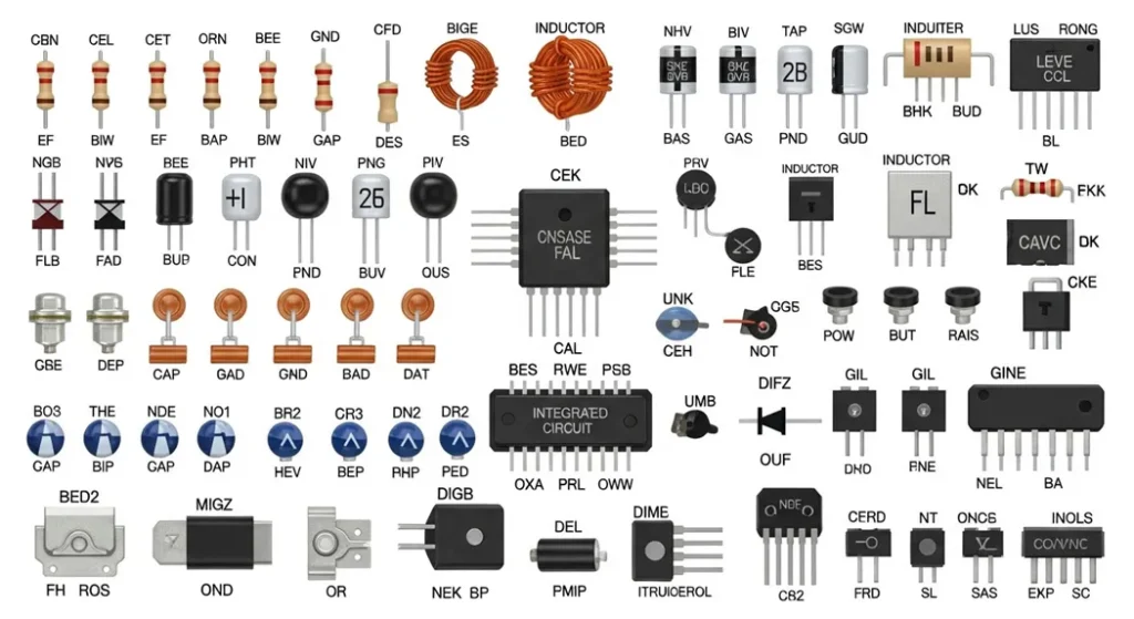
Electronic circuits rely on a range of components, each possessing a precise, quantifiable role. Resistors function to limit current flow (governed by Ohm’s Law) and, crucially, to dissipate power as heat, a characteristic calculated using the formula
P=I2R
for safe operation. Capacitors are energy storage elements that resist changes in voltage, a trait defined by the time constant
τ=RC
This makes them essential for smoothing voltage fluctuations in power supplies and controlling the blink rate in a simple timer circuit by governing the capacitor’s charge and discharge cycle. Inductors store energy in a magnetic field and are leveraged in circuits to filter signals. Diodes ensure current flows in only one direction, which is critical for AC-to-DC rectification.
Transistors are the workhorse active components, used either to amplify signals (in analog circuits) or to switch signals (forming the basis of digital logic). At a higher level of integration, Integrated Circuit (IC) chips combine millions of transistors and diodes onto a single piece of silicon. These highly complex chips function as Microcontrollers or Microprocessors, executing programmed instructions to power sophisticated devices like smart thermostats. The entire system is completed by input devices like Sensors, which detect environmental changes (e.g., temperature or light), and output devices like Displays (e.g., LEDs or LCDs) that provide visual feedback.
| Component | Function | Example Application |
|---|---|---|
| Resistor | Limits current | LED protection |
| Capacitor | Stores energy | Timing circuit |
| Transistor | Amplifies/switches | Logic gates |
| Diode | Unidirectional flow | Power rectification |
Designing Electronic Circuits
Designing a circuit starts with an electronic circuit drawing online a blueprint showing how components connect. Tools like Easy EDA or Altium Designer simplify this process, allowing engineers to create and simulate circuits before building. For instance, designing a simple LED circuit involves selecting a resistor to limit current, calculated using Ohm’s Law ( R=Vsource−VLEDILED ). A 5V supply, 2V LED, and 20mA current yield a 150Ω resistor.
PCB design follows, translating the schematic into a physical layout. Signal integrity is crucial poor layouts can cause noise or interference. Beginners often overlook grounding, leading to unstable circuits. Using ground planes and minimizing trace lengths can mitigate these issues. Tools like EasyEDA offer simulation features to test designs, ensuring reliability before manufacturing.
Step-by-Step Example: LED Circuit Design
- Choose an LED (e.g., 2V, 20mA).
- Select a power source (e.g., 5V battery).
- Calculate resistor value:
R=5−20.02=150Ω. - Draw the schematic in EasyEDA, connecting the LED, resistor, and battery.
- Simulate to verify current flow.
- Design a PCB layout, ensuring short traces and proper grounding.
- Prototype and test the circuit.
| Design Step | Tool/Consideration | Purpose |
|---|---|---|
| Schematic | EasyEDA | Plan connections |
| Simulation | Altium Designer | Verify functionality |
| PCB Layout | Ground planes | Ensure signal integrity |
Breadboard vs PCB
| Aspect | Breadboard | PCB |
|---|---|---|
| Use | Prototyping | Permanent design |
| Reliability | Loose connections | Stable, manufacturable |
| Cost | Low | Higher (fabrication) |
| Signal Integrity | Poor at high freq | Good with ground planes |
Advanced Design Metrics and Future Trends
As operating frequencies increase, the physical layout of a circuit becomes as critical as the schematic, driving demand for expertise in advanced design metrics.
Signal Integrity (SI) and PCB Standards
At high clock speeds (GHz), conductors on a PCB behave as transmission lines, not ideal wires. Signal Integrity (SI) is the measure of signal quality, preventing issues like reflection and crosstalk.
- Crosstalk: Unwanted electromagnetic coupling between adjacent traces, corrupting digital signals.
- Impedance Matching: Essential for high-frequency signal transmission to prevent signal reflections that cause errors.
- IPC-A-610: The globally recognized standard for the acceptability of electronic assemblies, cited by manufacturers and quality control engineers for PCB manufacturing and soldering criteria.
Future Trend: Edge AI Circuits
A major focus for high-density integrated circuits is Edge AI, where processing is moved from the cloud to the device itself (the “edge”). This relies on highly efficient, low-power mixed-signal chips capable of executing machine learning models directly on sensors (e.g., smart cameras, industrial IoT devices).
This shift requires unprecedented integration of high-speed digital processing and ultra-low-power analog front-ends, pushing the limits of modern semiconductor fabrication (3 nm and beyond).
Troubleshooting and Measurement Devices
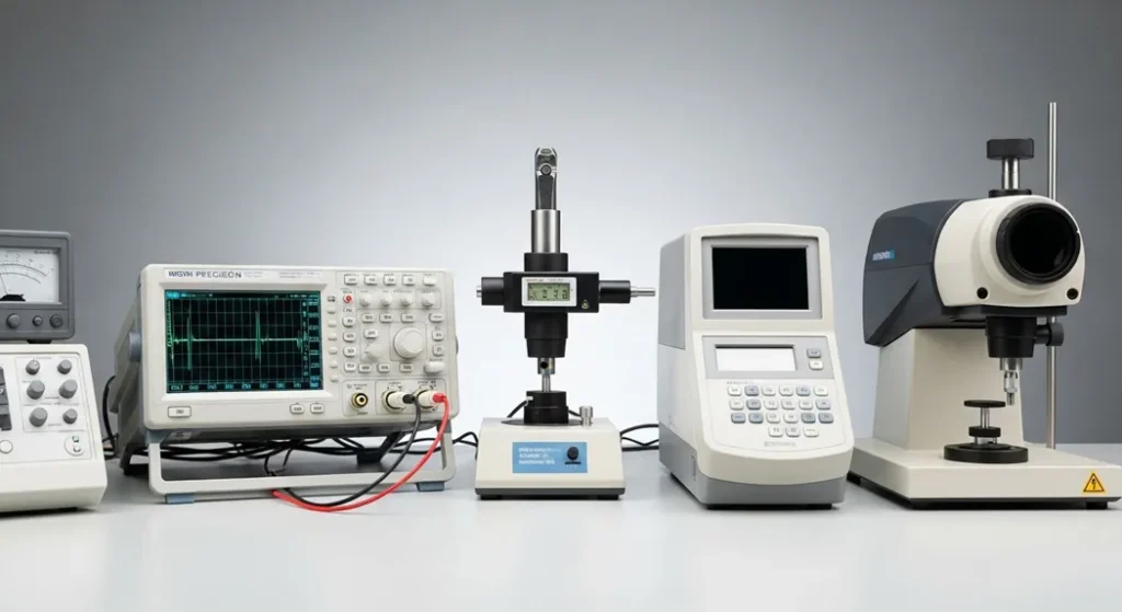
Testing circuits ensures they perform as intended. Oscilloscopes visualize voltage changes, helping diagnose issues like signal distortion in an audio circuit. Multimeters measure voltage, current, and resistance, essential for troubleshooting. Signal generators provide test signals to evaluate circuit response, while logic analyzers debug digital circuits by tracking signal states. For example, an oscilloscope can reveal voltage spikes in a power supply, guiding engineers to add capacitors for stabilization.
Practical tip: When using a multimeter, always start with the highest range to avoid damage. Beginners often misread oscilloscope scales, mistaking millivolts for volts, leading to incorrect conclusions. Calibration is key to accurate measurements.
| Device | Function | Application |
|---|---|---|
| Oscilloscope | Visualizes signals | Signal debugging |
| Multimeter | Measures electrical properties | Troubleshooting |
| Signal Generator | Provides test signals | Circuit testing |
Applications of Electron Devices and Circuits
Electron devices and circuits power countless applications. In consumer electronics, microcontrollers in smart thermostats optimize energy use. Industrial automation relies on circuits for robotic control systems, improving efficiency. Medical devices, like MRI machines, use analog circuits for precise imaging. Telecommunications depend on mixed-signal circuits in 5G modems, enabling high-speed data transfer. As of 2025, advancements in low-power circuits have revolutionized wearables, like health monitors that track vital signs in real time.
Real-world example: A smart thermostat uses a microcontroller to process sensor data, adjusting temperature based on user preferences. This integration of sensors, microcontrollers, and displays showcases the versatility of electron devices and circuits.
| Application | Key Devices | Impact |
|---|---|---|
| Consumer Electronics | Microcontrollers | Smart devices |
| Medical Devices | Analog circuits | Precision diagnostics |
| Telecommunications | Mixed-signal ICs | High-speed connectivity |
Reliability and Industry Standards (E-E-A-T)
For critical applications (aerospace, medical, automotive), semiconductor and circuit performance must comply with rigorous international standards to ensure safety and long-term reliability.
Semiconductor Testing and Qualification
- JEDEC Standards (e.g., JESD47): These standards define the stress tests (thermal cycling, humidity, high-temperature operation) required to qualify a semiconductor device before it can be used commercially.
- AEC-Q100: The critical qualification standard for integrated circuits used in Automotive Applications, specifying extended temperature ranges and reliability requirements far stricter than consumer electronics.
Circuit Design and Safety
- IEEE Standards: Govern circuit simulation models (e.g., SPICE models for transistors) and define acceptable parameters for power quality and electromagnetic compatibility (EMC).
- IEC 60601 Series: The fundamental set of standards governing the design and safety requirements for Medical Electrical Equipment, ensuring patient protection against electric shock and device failure.
Conclusion
Electron devices and circuits are the unsung heroes of modern technology, enabling everything from simple gadgets to life-saving medical equipment. By understanding their types, components, and applications, you can unlock the potential to create or innovate. Whether you’re a hobbyist building a DIY project or a professional designing a PCB, the principles of electron devices and circuits are your foundation. Explore further with tools like EasyEDA or courses on electronics to deepen your knowledge. Visit [YourWebsite] for PCB design resources and start building today.
FAQ (Frequently Asked Questions)
Q: What are electron devices and circuits?
A: Electron devices manipulate electron flow to perform tasks, while circuits are closed-loop systems of these devices.
Q: What are the types of electronic components?
A: Passive (resistors, capacitors), active (transistors, diodes), and electromechanical (relays, motors).
Q: How do resistors work in a circuit?
A: Resistors limit current flow, protecting components or controlling voltage. Governed by Ohm’s Law (V=IR).
Q: What is the Shockley diode equation used for?
A: It models the exponential I–V relationship of diodes, critical for rectifiers and logic gates.
Q: What is the RC time constant in capacitors?
A: τ = RC defines how quickly a capacitor charges/discharges, key for filters and timers.
Q: What is ripple factor in rectifiers?
A: Ripple factor (γ = Vrms/Vdc) measures DC output quality; lower values mean cleaner power.
Q: What are JEDEC standards in semiconductors?
A: JEDEC defines stress tests and reliability protocols for qualifying semiconductor devices.
Q: What is Edge AI in circuits?
A: Edge AI uses low-power mixed-signal ICs to run ML models directly on sensors/devices.
Q: What is the difference between analog and digital circuits?
A: Analog circuits process continuous signals; digital circuits process discrete 0/1 signals.
Q: How does a transistor amplify signals?
A: A small base current controls a larger collector current, defined by gain β = Ic/Ib.
Q: How do you design a PCB for beginners?
A: Start with schematic, simulate, then layout PCB with ground planes and short traces.
Q: Why is impedance matching important?
A: Prevents reflections in high-frequency circuits, ensuring signal integrity and accuracy.
Q: What is the role of op-amps in medical imaging?
A: Op-amps amplify weak analog signals for precise diagnostics in imaging equipment.
Q: What is the difference between breadboard and PCB?
A: Breadboards are for prototyping; PCBs are permanent, reliable, and manufacturable.
Q: How do capacitors smooth voltage in power supplies?
A: They store charge and release it to reduce ripple, stabilizing DC output.