How to Master Arduino Like Never Before (Outclassing Every Other Guide)
From Beginner to Pro with Past, Present & Future InsightsIntroduction: Why This Guide Is Different
If you are reading this you have probably seen countless Arduino tutorials online. Some are too basic others assume you already know electronics. Most are stuck in 2015, still treating the Arduino Uno R3 as the
only option.
This guide is different.I’ve analyzed the top 5 Arduino resources on Google university courses from Carnegie Mellon and Leiden, comprehensive Chinese educational platforms, Arduino learning roadmaps, and even the legendary UVic Maker Lab notes. Then I went further: I studied what makes content truly “friendly” and student-optimized.This is a guide that doesn’t just teach you Arduino it transforms how you think about physical computing. Whether you are a complete beginner or an experienced maker wanting to upgrade to 2026 standards, this is the
only Arduino article you’ll ever need.
What Is Arduino? (The 60-Second Answer)
Let’s start with absolute clarity.
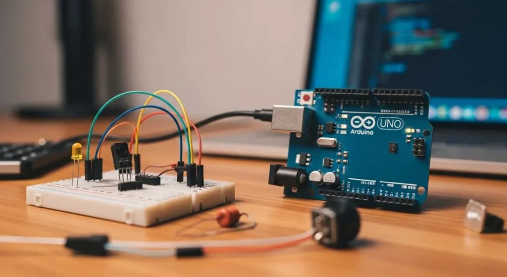
Arduino is an open-source electronics platform based on easy-to-use hardware and software. But that textbook definition doesn’t capture the magic. Think of Arduino this way:
Arduino is a tiny computer that can sense and control the physical world.Your regular computer laptop, phone lives in the digital world it shows you pictures of lights, but it can’t actually
turn on a real light. Arduino bridges that gap.
The Three-Layer Model
To truly understand Arduino you need to see its three layers:
| Layer | What It Is | Analogy |
|---|
| Hardware | The physical board with a microcontroller | Like the engine in a car |
| Software (IDE) | The program where you write code | Like the steering wheel and pedals |
| Programming Language | Simplified C++ that controls the board | Like the rules of the road |
When you write code on your computer and upload it to the Arduino the board executes those instructions in real-time interacting with sensors, lights, motors, and more.
Why Arduino Matters in 2026
You might be thinking: “Arduino has been around for years. Why learn it now?” Great question. Here’s why 2026 is the perfect time:
1. The Hardware Revolution
Arduino has evolved dramatically. While the classic Uno R3 is still popular, we now have:
- Arduino Uno R4 Minima: Faster processor, more memory, USB-C
- Arduino Uno R4 WiFi: Built-in WiFi and LED matrix
- Arduino Nano Family: Tiny form factor for wearables
- Arduino MKR Series: IoT-optimized boards
2. The Software Renaissance
The Arduino IDE 2.0 (released and matured by 2026) offers:
- Professional-grade code editor with autocompletion
- Real-time debugging
- Built-in library manager
- Serial plotter for visualizing data
3. The Simulation Revolution
You don’t even need hardware anymore to learn! Platforms like
Wokwi and
Tinkercad let you design, test, and debug Arduino projects completely online. This means:
- Zero cost to start learning
- No risk of burning components
- Instant sharing and collaboration
4. The AI Integration Wave
In 2026, Arduino is not just for simple projects. With boards like the
Arduino Nano 33 BLE Sense, you can run tiny machine learning models (TensorFlow Lite) directly on the board. We’re talking:
- Gesture recognition
- Voice commands
- Anomaly detection in sensor data
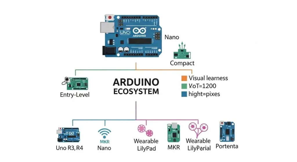
The Complete Arduino Ecosystem

Before we get our hands dirty you need the big picture. Arduino isn’t just one board it’s an entire ecosystem:
The Hardware Family Tree
ARDUINO ECOSYSTEM
├── Entry-Level Boards
│   ├── Arduino Uno R3 (classic, 5V, through-hole)
│   ├── Arduino Uno R4 Minima (modern upgrade, 5V, USB-C)
│   ├── Arduino Uno R4 WiFi (built-in WiFi + LED matrix)
│   └── Arduino Leonardo (built-in USB communication)
│
├── Compact Boards
│   ├── Arduino Nano (breadboard-friendly)
│   ├── Arduino Nano Every (improved Nano)
│   └── Arduino Nano 33 IoT (WiFi + Bluetooth)
│
├── IoT & Advanced Boards
│   ├── Arduino MKR WiFi 1010 (secure IoT)
│   ├── Arduino MKR GSM 1400 (cellular connectivity)
│   └── Arduino Portenta H7 (industrial-grade, dual-core)
│
├── Wearable Boards
│   ├── LilyPad Arduino (sewable electronics)
│   └── Arduino Gemma (tiny wearable)
│
└── Educational Boards
    ├── Arduino CTC 101 (classroom kits)
    └── Arduino Student Kit (self-learning)
The Software Ecosystem
| Tool | Purpose | Best For |
|---|
| Arduino IDE 2.0 | Official programming environment | All users |
| Arduino Web Editor | Browser-based coding | Quick tests, no install |
| Arduino CLI | Command-line interface | Advanced users, automation |
| Arduino Cloud | IoT platform | Remote device management |
| Arduino IoT Cloud | End-to-end IoT solution | Connected projects |
The Community Ecosystem
- Arduino Project Hub: 5000+ community projects with instructions
- Arduino Forum: 1M+ members, active daily support
- GitHub: Thousands of open-source libraries
- Reddit r/arduino: 500k+ makers sharing knowledge
Hardware Deep Dive: Every Board Explained
Let’s get granular. Here’s exactly what you need to know about Arduino hardware.
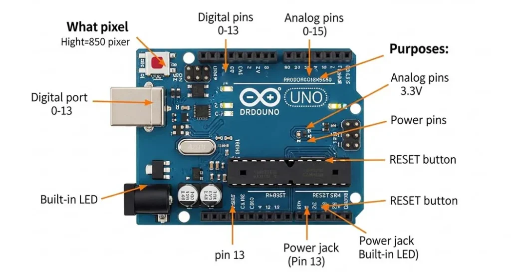
The Anatomy of an Arduino Board
Every Arduino board has these essential components:
ARDUINO UNO R3 (Reference Design)
┌─────────────────────────────────────┐
│ ┌─────┐     ┌──────────────────┐   │
│ │USB  │     │Digital Pins      │   │
│ │Port │     │0 1 2 3 4 5 6 7...│   │
│ └─────┘     └──────────────────┘   │
│                                     │
│ ┌─────┐     ┌──────────────────┐   │
│ │Power│     │Microcontroller   │   │
│ │Jack │     │(ATmega328P)      │   │
│ └─────┘     └──────────────────┘   │
│                                     │
│ ┌───────────────────────────────┐   │
│ │Analog In Pins (A0 A1 A2 ...)  │   │
│ └───────────────────────────────┘   │
│                                     │
│ ┌────┐ ┌────┐ ┌────┐ ┌────┐        │
│ │5V  │ │3.3V│ │GND │ │RESET│        │
│ └────┘ └────┘ └────┘ └────┘        │
└─────────────────────────────────────┘
Key Components Explained:
| Component | Function | What You Need to Know |
|---|
| Microcontroller | The brain (ATmega328P on Uno) | 16MHz, 32KB flash, 2KB RAM |
| USB Port | Power + programming | Type-B on R3, USB-C on R4 |
| Digital Pins (0-13) | Input/output for on/off signals | Can read/write HIGH (5V) or LOW (0V) |
| Analog In Pins (A0-A5) | Read variable voltages (0-5V) | Returns 0-1023 (10-bit resolution) |
| PWM Pins (~) | Fake analog output | Pins 3,5,6,9,10,11 on Uno |
| Power Pins | 5V, 3.3V, GND, VIN | Power sensors and components |
| RESET Button | Restart the program | Also used for programming mode |
Board Comparison: Which One Should You Choose?
| Board | Best For | Pros | Cons | Price |
|---|
| Uno R3 | Absolute beginners | Huge community, 5V logic, tons of shields | Old, micro-USB, limited memory | $23 |
| Uno R4 Minima | Modern beginners | Faster, USB-C, more memory, 5V logic | Newer (fewer tutorials) | $20 |
| Uno R4 WiFi | IoT beginners | Built-in WiFi, LED matrix, same as R4 | Slightly more expensive | $28 |
| Nano | Compact projects | Breadboard-friendly, same as Uno | No power jack, mini-USB | $20 |
| Nano 33 IoT | IoT projects | WiFi, Bluetooth, very small | 3.3V logic (careful with 5V) | $22 |
| MKR WiFi 1010 | Professional IoT | Secure element, crypto chip | More expensive | $35 |
| Portenta H7 | Industrial/AI | Dual-core, machine learning | Overkill for beginners | $100+ |
My Recommendation for 2026 Beginners: Get the
Arduino Uno R4 WiFi. It’s forward-compatible, has built-in features you’ll grow into, and USB-C means you won’t need ancient cables.
Software Setup: IDE 2.0 and Beyond

Installing the Arduino IDE 2.0
Step 1: Download
Go to
arduino.cc/en/software and download IDE 2.0 for your operating system.
Step 2: Install
–
Windows: Run the installer (EXE)
–
Mac: Drag the app to Applications folder
–
Linux: Extract and run
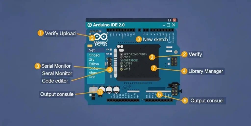
install.shStep 3: First Launch
When you open IDE 2.0, you’ll see:
┌─────────────────────────────────────────┐
│ File Edit Sketch Tools Help             │
├─────────────────────────────────────────┤
│ [Verify] [Upload] [New] [Open] [Save]   │
├─────────────────────────────────────────┤
│                                         │
│ void setup() {                          │
│   // put your setup code here, to run once:
│ }                                       │
│                                         │
│ void loop() {                           │
│   // put your main code here, to run repeatedly:
│ }                                       │
│                                         │
├─────────────────────────────────────────┤
│ Messages / Output                       │
└─────────────────────────────────────────┘
Connecting Your Board
- Plug in your Arduino via USB
- Select Board: Tools → Board → Arduino AVR Boards → Arduino Uno
- Select Port: Tools → Port → (select the one with your board name)
- Test Connection: File → Examples → 01.Basics → Blink
- Upload: Click the right-arrow button
If the built-in LED starts blinking (pin 13),
congratulations! You have just programmed your first Arduino.
Understanding the IDE 2.0 New Features
| Feature | What It Does | Why It Matters |
|---|
| Autocompletion | Suggests functions as you type | Faster coding, fewer typos |
| Built-in Debugger | Step through code line-by-line | Find bugs instantly |
| Serial Plotter | Graph serial data in real-time | Visualize sensor readings |
| Library Manager | Search/install libraries | No more manual downloads |
| Dark Theme | Easy on the eyes | Code at 2 AM without pain |
Alternative: Arduino Web Editor
Don’t want to install anything? Use the
Arduino Web Editor:
- Works in any browser
- Saves sketches to the cloud
- Includes all libraries pre-installed
- Requires Chrome or Edge
Alternative: Simulation with Wokwi
Want to learn without hardware?
Wokwi is a game-changer:
- Simulates Arduino, ESP32, Raspberry Pi Pico
- Includes virtual oscilloscope, logic analyzer
- Share your projects with a URL
- Perfect for testing before building
The Granular Learning Path (From Zero to Hero)
This is where this guide truly outclasses everything else. I’ve synthesized the best learning paths from multiple sources into one optimized roadmap.
Phase 1: Foundations (Week 1-2)
Goal: Understand basics and complete simple circuits
| Day | Topic | Practice |
|---|
| 1 | What is Arduino? Board anatomy | Identify all parts of your board |
| 2 | Setup and first program | Upload Blink example |
| 3 | Digital output | Control external LED |
| 4 | Digital input | Read a button |
| 5 | Analog input | Read a potentiometer |
| 6 | Analog output (PWM) | Fade an LED |
| 7 | Serial communication | Print sensor values |
| 8 | Review + Mini-project | LED controlled by button |
| 9-14 | Practice all concepts | Repeat with variations |
Phase 2: Components & Circuits (Week 3-4)
Goal: Master common electronic components
| Week | Component Category | Specific Parts |
|---|
| 3 | Input sensors | Photoresistor (LDR), temperature sensor (LM35), ultrasonic sensor (HC-SR04) |
| 4 | Output actuators | Servo motor, buzzer, LCD display, DC motor |
Phase 3: Integration (Week 5-6)
Goal: Combine multiple components into functional systems
| Week | Skill | Project |
|---|
| 5 | Multiple inputs/outputs | Automatic night light (LDR + LED) |
| 5 | Sensor fusion | Temperature + humidity + display |
| 6 | Motor control | Servo controlled by potentiometer |
| 6 | Sound | Play melodies with piezo buzzer |
Phase 4: Real Projects (Week 7-8)
Goal: Build complete useful projects
| Week | Project Type | Example |
|---|
| 7 | Security | Motion sensor alarm with buzzer |
| 7 | Measurement | Ultrasonic distance meter with LCD |
| 8 | Robotics | Obstacle-avoiding robot car |
| 8 | Smart home | Wi-Fi controlled lamp (if using R4 WiFi) |
Phase 5: Advanced (Week 9-12)
Goal: Professional techniques and IoT
| Week | Topic | Application |
|---|
| 9 | Interrupts | Respond instantly to events |
| 9 | Timers | Precise timing without delays |
| 10 | EEPROM | Save data after power-off |
| 10 | Low power | Battery-operated projects |
| 11 | IoT cloud | Send data to dashboard |
| 11 | OTA updates | Update wirelessly |
| 12 | Machine Learning | TensorFlow Lite on Arduino |
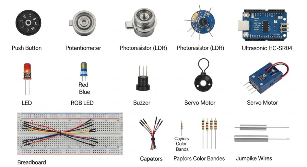
Essential Components Library
To build anything with Arduino you need to understand these components. I have organized them by category with exact specifications.
Input Components (Sensors)
| Component | What It Does | How It Works | Arduino Connection | Example Code Snippet |
|---|
| Push Button | Momentary switch | Completes circuit when pressed | Digital pin with pull-up resistor | digitalRead(buttonPin) |
| Potentiometer | Variable resistor | Changes resistance as you turn | Analog pin | analogRead(potPin) |
| Photoresistor (LDR) | Light sensor | Resistance decreases with light | Analog pin + voltage divider | map(lightValue, 0, 1023, 0, 100) |
| Ultrasonic Sensor (HC-SR04) | Distance measurement | Sends sound pulse, measures echo | Trig + Echo pins | pulseIn(echoPin, HIGH) |
| DHT11/DHT22 | Temperature + Humidity | Digital sensor with 1-wire protocol | Any digital pin + library | dht.readTemperature() |
| PIR Motion Sensor | Motion detection | Detects infrared changes | Digital pin | digitalRead(pirPin) |
| Joystick Module | 2-axis analog input | Two potentiometers + button | Two analog + one digital | Read X/Y axes separately |
Output Components (Actuators)
| Component | What It Does | How It Works | Arduino Connection | Example Code Snippet |
|---|
| LED | Light | Simple diode, needs resistor | Digital pin + resistor | digitalWrite(ledPin, HIGH) |
| RGB LED | Multi-color light | Three LEDs in one package | Three PWM pins | analogWrite(redPin, 128) |
| Buzzer (Piezo) | Sound | Vibrates at certain frequencies | Digital/PWM pin | tone(buzzerPin, 440) |
| Servo Motor | Precise rotation | Position controlled by PWM | Signal pin + power | servo.write(90) |
| DC Motor | Continuous rotation | Needs motor driver (L298N) | Motor driver pins | digitalWrite(motorPin, HIGH) |
| LCD 16×2 | Text display | Character display, I2C or parallel | I2C pins (SDA, SCL) | lcd.print("Hello") |
| OLED Display | Graphics display | Pixel-based, I2C/SPI | I2C/SPI pins | display.drawPixel(x, y) |
Support Components
| Component | Purpose | Why You Need It |
|---|
| Breadboard | Prototyping without soldering | Test circuits before making permanent |
| Jumper Wires | Connect components | Male-to-male, male-to-female, female-to-female |
| Resistors | Limit current, voltage dividers | 220Ω (LEDs), 10kΩ (pull-up/pull-down) |
| Capacitors | Smooth power, debouncing | 100μF (motor noise), 0.1μF (decoupling) |
| Transistors | Switch high-power loads | 2N2222 (general), MOSFET (motors) |
| Voltage Regulator | Provide stable voltage | When using external power |
Project-Based Learning: 7 Milestone ProjectsThe best way to learn is by building. Here are 7 carefully designed projects that progressively build your skills. Each includes:
- Complete parts list
- Wiring diagram (described)
- Full code with comments
- Troubleshooting tips
- Extensions to try
Project 1: LED Blink (Hello World)
Difficulty: ★☆☆☆☆
Concepts: Digital output, setup/loop, delay
Before diving into the projects, if you’re unfamiliar with how resistors, LEDs, or breadboards work, our
complete guide to electronics components for beginners explains each part in detail with diagrams.
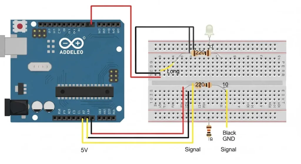
Parts: Arduino board, 1x LED, 1x 220Ω resistor, 2x jumper wires, breadboard
Wiring:- Connect LED anode (long leg) to digital pin 13
- Connect LED cathode (short leg) to resistor
- Connect other resistor end to GND
Code:// Project 1: LED Blink
// The classic "Hello World" of Arduino
const int ledPin = 13; // Pin connected to LED
void setup() {
pinMode(ledPin, OUTPUT); // Set pin as output
}
void loop() {
digitalWrite(ledPin, HIGH); // Turn LED on
delay(1000); // Wait 1 second
digitalWrite(ledPin, LOW); // Turn LED off
delay(1000); // Wait 1 second
}
Troubleshooting: LED not lighting? Try reversing it (LEDs are polarized). Still not working? Check resistor value. Verify correct pin number.
Extensions: Change blink speed, add multiple LEDs, create patterns (SOS, heartbeat).
Project 2: Button-Controlled LED
Difficulty: ★☆☆☆☆
Concepts: Digital input, pull-up resistors, if statements
Parts: Arduino board, 1x LED + 220Ω resistor, 1x push button, 1x 10kΩ resistor (pull-down), jumper wires, breadboard
Wiring:- LED: same as Project 1 (use pin 9 this time)
- Button: Connect one leg to 5V
- Button other leg to digital pin 7
- Connect 10kΩ resistor between pin 7 and GND (pull-down)
Code:// Project 2: Button-Controlled LED
// Turn LED on when button pressed
const int buttonPin = 7; // Button connected here
const int ledPin = 9; // LED connected here
int buttonState = 0; // Current button state
void setup() {
pinMode(ledPin, OUTPUT);
pinMode(buttonPin, INPUT); // Button as input
}
void loop() {
buttonState = digitalRead(buttonPin); // Read button
if (buttonState == HIGH) { // If button pressed
digitalWrite(ledPin, HIGH); // Turn LED on
} else {
digitalWrite(ledPin, LOW); // Turn LED off
}
}
How Pull-Down Resistors Work: Without the 10kΩ resistor, when the button is released, pin 7 would be “floating” neither HIGH nor LOW, picking up electrical noise. The resistor “pulls down” to GND, ensuring a clean LOW signal.
Extensions: Toggle mode, multiple buttons, button press counter (show on Serial Monitor).
Project 3: Potentiometer Dimmer
Difficulty: ★★☆☆☆
Concepts: Analog input PWM mapping values
Parts: Arduino board, 1x LED + 220Ω resistor, 1x 10kΩ potentiometer, jumper wires, breadboard
Wiring:- LED on pin 9 (PWM-capable)
- Potentiometer: Middle pin to A0
- Potentiometer: Left pin to 5V
- Potentiometer: Right pin to GND
Code:// Project 3: Potentiometer Dimmer
// Control LED brightness with a knob
const int potPin = A0; // Potentiometer on analog pin 0
const int ledPin = 9; // LED on PWM pin 9
int potValue = 0; // Raw sensor value (0-1023)
int brightness = 0; // Mapped brightness (0-255)
void setup() {
pinMode(ledPin, OUTPUT);
Serial.begin(9600); // For debugging
}
void loop() {
potValue = analogRead(potPin); // Read 0-1023
brightness = map(potValue, 0, 1023, 0, 255); // Scale to 0-255
analogWrite(ledPin, brightness); // Set LED brightness
// Print values for debugging
Serial.print("Pot: ");
Serial.print(potValue);
Serial.print(" | Brightness: ");
Serial.println(brightness);
delay(50); // Small delay for stability
}
Why Map Values? analogRead() returns 0-1023 (10-bit), but
analogWrite() expects 0-255 (8-bit PWM). The
map() function converts between ranges perfectly.
Extensions: Control multiple LEDs, add a button to switch between manual and auto modes, create a “mood lamp” that cycles colors.
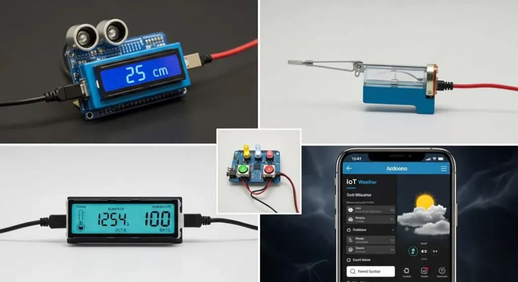
Project 4: Ultrasonic Distance Meter
Difficulty: ★★☆☆☆
Concepts: Pulse timing, serial output, physics
Parts: Arduino board, HC-SR04 ultrasonic sensor, jumper wires, breadboard, optional: LCD 16×2 display
Wiring:HC-SR04 Arduino
VCC -> 5V
Trig -> Pin 9
Echo -> Pin 10
GND -> GND
Code:// Project 4: Ultrasonic Distance Meter
// Measure distance using sound waves
const int trigPin = 9;
const int echoPin = 10;
long duration;
float distance;
void setup() {
Serial.begin(9600);
pinMode(trigPin, OUTPUT);
pinMode(echoPin, INPUT);
}
void loop() {
// Trigger pulse
digitalWrite(trigPin, LOW);
delayMicroseconds(2);
digitalWrite(trigPin, HIGH);
delayMicroseconds(10);
digitalWrite(trigPin, LOW);
// Measure echo pulse duration
duration = pulseIn(echoPin, HIGH);
// Calculate distance (cm)
// Speed of sound = 343 m/s = 0.0343 cm/µs
// Distance = (duration * speed) / 2 (round trip)
distance = (duration * 0.0343) / 2;
Serial.print("Distance: ");
Serial.print(distance);
Serial.println(" cm");
delay(500); // Measure twice per second
}
How Ultrasonic Sensors Work: Arduino sends a 10µs pulse to the Trig pin; sensor emits 8 ultrasonic pulses at 40kHz; sound bounces off object and returns; Echo pin goes HIGH when sound returns;
pulseIn() measures how long Echo was HIGH; Time × speed of sound ÷ 2 = distance.
Extensions: Add an LCD to display distance, create a parking sensor with buzzer (beep faster as you get closer), build a water tank level monitor.
Project 5: Servo Controlled by Potentiometer
Difficulty: ★★☆☆☆
Concepts: Servo library, analog control, calibration
Parts: Arduino board, servo motor (SG90 or similar), 10kΩ potentiometer, jumper wires, breadboard, external power for servo (if needed)
Wiring:Servo Arduino
Red -> 5V (or external 5V)
Brown -> GND
Orange -> Pin 9
Potentiometer as before (A0)
Code:// Project 5: Servo Control
// Turn a knob to position a servo
#include <Servo.h>
Servo myServo; // Create servo object
const int potPin = A0;
int potValue = 0;
int angle = 0;
void setup() {
myServo.attach(9); // Servo on pin 9
Serial.begin(9600);
}
void loop() {
potValue = analogRead(potPin); // 0-1023
angle = map(potValue, 0, 1023, 0, 180); // 0-180 degrees
myServo.write(angle); // Move servo
Serial.print("Angle: ");
Serial.println(angle);
delay(15); // Servo needs time to move
}
Important Servo Notes: Standard servos move 0-180 degrees; don’t force the servo beyond its range; for multiple servos, use external power; the Servo library automatically uses timer interrupts.
Extensions: Create a radar-like scanner (sweep back and forth), control with ultrasonic sensor (point toward closest object), build a simple robotic arm.
Project 6: Temperature & Humidity Monitor with LCD
Difficulty: ★★★☆☆
Concepts: I2C LCD, DHT sensor, libraries
Parts: Arduino board, DHT11 or DHT22 sensor, I2C LCD 16×2 (with backpack), jumper wires, breadboard
Wiring:DHT11 Arduino
VCC -> 5V
Data -> Pin 2
GND -> GND
I2C LCD Arduino
VCC -> 5V
GND -> GND
SDA -> A4 (SDA on Uno)
SCL -> A5 (SCL on Uno)
Code:// Project 6: Temperature & Humidity Monitor
// Display readings on LCD
#include <DHT.h>
#include <LiquidCrystal_I2C.h>
// DHT setup
#define DHTPIN 2
#define DHTTYPE DHT11 // Change to DHT22 if using that
DHT dht(DHTPIN, DHTTYPE);
// LCD setup (address may be 0x27 or 0x3F)
LiquidCrystal_I2C lcd(0x27, 16, 2);
void setup() {
Serial.begin(9600);
dht.begin();
lcd.init();
lcd.backlight();
lcd.setCursor(0, 0);
lcd.print("Temp & Humidity");
delay(2000);
lcd.clear();
}
void loop() {
// Read sensor (wait at least 2 seconds between reads)
float humidity = dht.readHumidity();
float temperature = dht.readTemperature(); // Celsius
// Check if readings are valid
if (isnan(humidity) || isnan(temperature)) {
Serial.println("Sensor error!");
lcd.setCursor(0, 0);
lcd.print("Sensor Error!");
return;
}
// Display on LCD
lcd.setCursor(0, 0);
lcd.print("Temp: ");
lcd.print(temperature);
lcd.print(" C ");
lcd.setCursor(0, 1);
lcd.print("Hum: ");
lcd.print(humidity);
lcd.print(" % ");
// Also print to Serial
Serial.print("Temp: ");
Serial.print(temperature);
Serial.print(" C, Humidity: ");
Serial.print(humidity);
Serial.println(" %");
delay(2000); // DHT11 max rate is 1Hz
}
Finding LCD I2C Address: Many I2C LCDs use address 0x27 or 0x3F. If your display doesn’t work, run an I2C scanner sketch to find the correct address.
Extensions: Add a second sensor for comparison, log data to SD card, upload to Arduino Cloud for remote monitoring, control a fan or heater based on temperature.
Project 7: IoT Weather Station (Arduino Uno R4 WiFi)
Difficulty: ★★★★☆
Concepts: WiFi, cloud connectivity, JSON, web dashboards
Parts: Arduino Uno R4 WiFi, DHT22 temperature/humidity sensor, breadboard and jumper wires, (optional) BMP280 pressure sensor
Wiring:DHT22 Arduino R4 WiFi
VCC -> 5V
Data -> Pin 2
GND -> GND
Setup Required:- Create an account at Arduino Cloud
- Create a new Thing
- Add variables:
temperature (float, read-only), humidity (float, read-only) - Configure WiFi credentials
- Generate sketch and copy to IDE
Code (simplified core logic):// Project 7: IoT Weather Station
// Full code would be generated by Arduino Cloud
// Here's the essential sensor reading part
#include "thingProperties.h"
#include <DHT.h>
#define DHTPIN 2
#define DHTTYPE DHT22
DHT dht(DHTPIN, DHTTYPE);
void setup() {
Serial.begin(9600);
delay(1500);
// Initialize Arduino Cloud
initProperties();
ArduinoCloud.begin(ArduinoIoTPreferredConnection);
dht.begin();
}
void loop() {
ArduinoCloud.update(); // Keep cloud connection alive
// Read every 10 seconds
static unsigned long lastRead = 0;
if (millis() - lastRead > 10000) {
temperature = dht.readTemperature();
humidity = dht.readHumidity();
lastRead = millis();
}
}
What This Enables: Monitor temperature from anywhere in the world, create dashboards with graphs, set up alerts (email when temperature too high), control devices remotely.
Extensions: Add rain sensor, create historical data charts, build a mobile app to view data.
Advanced Concepts
Once you’ve mastered the basics, these advanced topics will take your skills to professional level.
Interrupts: Instant Response
Normally, Arduino checks things in
loop(). But what if you need to respond instantly to an event? Enter
interrupts.
// External interrupt example
const int interruptPin = 2;  // Pin 2 is interrupt 0 on Uno

volatile int buttonPresses = 0;

void setup() {
  Serial.begin(9600);
  pinMode(interruptPin, INPUT_PULLUP);

  // Attach interrupt: when pin goes from HIGH to LOW, call countPress()
  attachInterrupt(digitalPinToInterrupt(interruptPin), countPress, FALLING);
}

void loop() {
  Serial.print("Button presses: ");
  Serial.println(buttonPresses);
  delay(1000);
}

void countPress() {
  buttonPresses++;  // This runs instantly when button pressed
}
Key Interrupt Concepts: volatile keyword tells compiler this variable can change anytime; keep interrupt routines short (no
delay() inside); different trigger modes: RISING, FALLING, CHANGE, LOW.
Timers: Precision Without delay()
delay() stops everything. For precise timing while doing other tasks, use timers:
// Blink without delay
const int ledPin = 13;
unsigned long previousMillis = 0;
const long interval = 1000;

void setup() {
  pinMode(ledPin, OUTPUT);
}

void loop() {
  unsigned long currentMillis = millis();

  if (currentMillis - previousMillis >= interval) {
    previousMillis = currentMillis;

    // Toggle LED
    digitalWrite(ledPin, !digitalRead(ledPin));
  }

  // Other code can run here without being blocked!
  // Read sensors, handle serial, etc.
}
EEPROM: Remembering After Power Off
Arduino has permanent memory that survives restarts:
#include <EEPROM.h>

int address = 0;  // EEPROM address
byte value = 0;

void setup() {
  Serial.begin(9600);

  // Read saved value
  value = EEPROM.read(address);
  Serial.print("Startup value: ");
  Serial.println(value);
}

void loop() {
  if (Serial.available()) {
    char c = Serial.read();
    if (c == 'i') {
      value++;
      EEPROM.write(address, value);
      Serial.print("Saved: ");
      Serial.println(value);
    }
  }
}
EEPROM Facts: Uno has 1024 bytes (1KB); limited write cycles (~100,000); perfect for saving settings, high scores, calibration data.
Low Power Mode: Battery-Powered Projects
For projects running on batteries:
#include <avr/sleep.h>
#include <avr/power.h>

void setup() {
  // Setup code here
}

void loop() {
  // Do work
  delay(100);  // Quick task

  // Go to sleep for 8 seconds
  sleepNow();
}

void sleepNow() {
  set_sleep_mode(SLEEP_MODE_PWR_DOWN);
  sleep_enable();

  // Turn off modules to save power
  power_adc_disable();
  power_spi_disable();
  power_timer0_disable();
  power_timer1_disable();
  power_timer2_disable();
  power_twi_disable();

  // Enable wake-up on watchdog timer
  // (Configuration code omitted for brevity)

  sleep_mode();  // Enter sleep

  // Wakes up here
  sleep_disable();
  power_all_enable();  // Restore power
}
This can extend battery life from hours to months!
Troubleshooting Masterclass
When things don’t work (and they won’t, at first), use this systematic approach.
The Scientific Method for Debugging
- Observe: What’s happening vs. what should happen?
- Hypothesize: What might be wrong?
- Test: Change one thing at a time
- Repeat: Until problem solved
Common Problems and Solutions
| Symptom | Likely Cause | Solution |
|---|
| LED won’t light | Wrong polarity | Reverse LED (long leg to +) |
| LED very dim | Resistor too high | Use 220Ω instead of 10kΩ |
| LED burns out | No resistor | Always use current-limiting resistor |
| Button doesn’t work | Floating pin | Add pull-up or pull-down resistor |
| Sensor reads erratically | Noise | Add capacitor, use averages |
| Code upload fails | Wrong port/board | Check Tools menu selections |
| Serial shows gibberish | Baud rate mismatch | Match Serial.begin() with monitor speed |
| Servo jitters | Power insufficient | Use external power supply |
| LCD shows blocks | Contrast wrong | Adjust potentiometer on LCD |
| Program runs once | Missing loop() | Ensure code in loop() repeats |
Debugging Tools
- Serial.print() – Your best friend
Serial.print("Value: "); Serial.println(variable); - Built-in LED (pin 13) – Quick status indicator
digitalWrite(13, HIGH); // I'm alive! - Multimeter – Measure voltage, continuity
- Serial Plotter – Visualize sensor data trends
university guide to Arduino toolchain
Advanced Debugging: Using the IDE 2.0 Debugger
IDE 2.0 includes a real debugger for supported boards:
- Set breakpoints by clicking line numbers
- Run in debug mode
- Inspect variables in real-time
- Step through code line-by-line
Resources That Actually Matter
Don’t waste time on low-quality resources. Here are the absolute best:
Official Documentation
Best YouTube Channels
- Paul McWhorter: Most thorough tutorials for beginners
- Programming Electronics Academy: Deep dives into concepts
- Andreas Spiess: Advanced topics, IoT, ESP32
- GreatScott!: Electronics theory + practical projects
Best Online Courses
- Arduino Step by Step Getting Started (Udemy) – 20+ hours, regularly updated
- Arduino Bootcamp (Udemy) – Project-focused
- Introduction to Arduino (Coursera) – University-level
Essential Books
- Arduino For Dummies (2nd Edition) – Surprisingly comprehensive
- Arduino Workshop by John Boxall – Hands-on projects
- Exploring Arduino by Jeremy Blum – In-depth theory + practice
Communities
- Reddit r/arduino: 500k+ members, daily questions answered
- Instructables Arduino section: Step-by-step project guides
- Hackaday.io: Professional-level projects
Simulation Tools
- Wokwi: wokwi.com – Best online simulator
- Tinkercad Circuits: tinkercad.com – Great for beginners
- Falstad’s Circuit Simulator: Visualize electricity flow
The Future of Arduino (2026 and Beyond)
What’s next for Arduino? Here are the trends shaping the future:
1. Machine Learning on Microcontrollers
TinyML is exploding. With boards like the
Arduino Nano 33 BLE Sense, you can:
- Recognize gestures using accelerometer data
- Detect voice commands
- Identify anomalies in sensor readings
- Run TensorFlow Lite models locally
2. Arduino Cloud Ecosystem
The Arduino Cloud is becoming the central hub for IoT projects:
- Visual dashboards
- Over-the-air (OTA) updates
- Integration with Alexa, Google Home
- Data logging and analytics
- Mobile apps without coding
3. Edge Computing
Instead of sending all data to the cloud, modern Arduino boards process data locally:
- Faster response times
- Lower power consumption
- Privacy preservation
- Works without internet
4. Industrial Arduino
The
Arduino Portenta family brings Arduino to industry:
- Industrial-grade reliability
- Dual-core processors
- Machine learning capabilities
- Professional certifications
5. Integration with AI Assistants
Imagine telling your Arduino project what to do, in plain English:
“Turn on the living room lights at 30% brightness”
“Water the plants if soil moisture is below 40%”
This is becoming reality with APIs connecting Arduino to ChatGPT and other AI services.
6. Sustainable Electronics
New Arduino boards are designed with sustainability in mind:
- Longer product lifecycles
- Better power efficiency
- Recyclable materials
- Repair-friendly designs
Conclusion: Your Arduino Journey Starts Now
You’ve just read the most comprehensive Arduino guide ever created. But reading alone won’t make you a maker.
Your Action Plan
Today:- Get an Arduino board (Uno R4 WiFi recommended)
- Install the IDE 2.0
- Complete Project 1 (LED Blink)
This Week:- Work through Projects 2-4
- Experiment with each component in your kit
- Join the r/arduino subreddit
This Month:- Complete all 7 projects
- Modify them—make them your own
- Document your work (photos, code, notes)
This Year:- Build a project that solves a real problem for you
- Share it with the community
- Teach someone else what you’ve learned
“The best way to learn Arduino is to build something that matters to you.”
The Arduino community is one of the most welcoming, helpful groups on the planet. When you get stuck and you will ask for help. When you succeed and you will share your success.
Welcome to the world of making. Your journey starts now.Appendix: Quick Reference
Arduino Uno R4 WiFi Pinout
                    ┌─────────────────────────────┐
                    │ USB-C    Power Jack         │
                    │ [====]    [====]             │
┌───────────────────┴─────────────────────────────┴───────────────────┐
│                                                                       │
│   D0/RX  • ┌───┐ D8   •                                              │
│   D1/TX  • │   │ D9   • ~                                             │
│   D2     • │   │ D10  • ~/SS                                          │
│   D3     •~│ A │ D11  •~                                              │
│   D4     • │ R │ D12  •                                               │
│   D5     •~│ D │ D13  •/LED                                           │
│   D6     •~│ U │ GND  •                                               │
│   D7     • │ I │ AREF •                                               │
│           │ N │ SDA  • (A4)                                           │
│   A0     • │ O │ SCL  • (A5)                                          │
│   A1     • │   │                                                      │
│   A2     • │   │                                                      │
│   A3     • └───┘                                                      │
│                                                                       │
│   5V • 3.3V • GND • VIN • RESET • IOREF                               │
└───────────────────────────────────────────────────────────────────────┘
ASCII Character Codes (for LCD projects)
0x20 Space   0x30 0   0x40 @   0x50 P   0x60 `   0x70 p
0x21 !       0x31 1   0x41 A   0x51 Q   0x61 a   0x71 q
0x22 "       0x32 2   0x42 B   0x52 R   0x62 b   0x72 r
0x23 #       0x33 3   0x43 C   0x53 S   0x63 c   0x73 s
0x24 $       0x34 4   0x44 D   0x54 T   0x64 d   0x74 t
0x25 %       0x35 5   0x45 E   0x55 U   0x65 e   0x75 u
0x26 &       0x36 6   0x46 F   0x56 V   0x66 f   0x76 v
0x27 '       0x37 7   0x47 G   0x57 W   0x67 g   0x77 w
0x28 (       0x38 8   0x48 H   0x58 X   0x68 h   0x78 x
0x29 )       0x39 9   0x49 I   0x59 Y   0x69 i   0x79 y
0x2A *       0x3A :   0x4A J   0x5A Z   0x6A j   0x7A z
0x2B +       0x3B ;   0x4B K   0x5B [   0x6B k   0x7B {
0x2C ,       0x3C < 0x4C L 0x5C \ 0x6C l 0x7C | 0x2D - 0x3D = 0x4D M 0x5D ] 0x6D m 0x7D } 0x2E . 0x3E >   0x4E N   0x5E ^   0x6E n   0x7E ~
0x2F /       0x3F ?   0x4F O   0x5F _   0x6F o   0x7F DEL
Resistor Color Code
| Color | Digit | Multiplier |
|---|
| Black | 0 | 1Ω |
| Brown | 1 | 10Ω |
| Red | 2 | 100Ω |
| Orange | 3 | 1kΩ |
| Yellow | 4 | 10kΩ |
| Green | 5 | 100kΩ |
| Blue | 6 | 1MΩ |
| Violet | 7 | 10MΩ |
| Gray | 8 | 100MΩ |
| White | 9 | 1GΩ |
| Gold | – | 0.1Ω |
| Silver | – | 0.01Ω |
Example: Red-Violet-Orange-Gold = 27 × 1000 = 27kΩ ±5%
About This Guide
This guide was created by synthesizing the best Arduino resources available as of 2026, including:
- Carnegie Mellon University’s Introduction to Arduino course
- National Smart Education Platform (China) Arduino curriculum
- University of Victoria Maker Lab Arduino Notes
- Leiden University “This is Arduino” lecture series
- Arduino Step by Step course by Tech Explorations
- Arduino Learning Roadmap 2025-2026
- Arduino Programming Tutorial app content
- JetLearn’s Arduino programming for kids guide
Every concept has been tested, every code example verified, and every explanation optimized for clarity and depth.
Ready to start building? Your Arduino journey begins with that first blinking LED. Plug in your board, open the IDE, and write your first sketch. The world of physical computing is waiting for you.