Key Takeaways Electronic Circuits Explained
An electronic circuit is simply a group of basic components such as resistors, capacitors, diodes, transistors, and IC. Connected together to control electricity and perform a task like lighting an LED, sensing a signal, amplifying sound, or processing logic. For beginners the best approach is to start with very simple projects like LED, sensor, and 555 timer circuits, practice first on a breadboard, and then move to PCBs. While learning how to read schematics, symbols, polarity, and series/parallel connections including the basic rule that when resistors are connected end-to-end (in series), the same current flows through each one and their values add up (Rtotal = R1 + R2 + R3), which increases total resistance and limits current flow. To keep circuits safe and reliable, focus on a few key rules: use Ohm’s Law to choose correct resistor values, check power dissipation to avoid overheating, and add decoupling capacitors and proper grounding to reduce noise. By following these fundamentals and standard PCB practices, anyone can confidently understand schematics, build reliable circuits, and progress to real-world electronic projects.
Introduction to Electronic Circuits
Electronics can feel intimidating, but starting with simple electronic circuits is an engaging way to explore this dynamic field. Whether you’re a hobbyist, student, or curious about how electrical circuits power everyday devices, mastering electronics circuits is your gateway to innovation. This guide demystifies electronic circuits, teaching you to read and create simple circuit diagrams, understand components like resistors in series, resistors in parallel, and integrated circuits, and build hands-on projects. From LED circuits to digital circuits, we’ll provide step-by-step instructions for beginner-friendly electronic projects. Our aim is to show with practical, detailed content, including insights into printed PCB design and PCB circuit boards. Let’s spark your electronics journey!
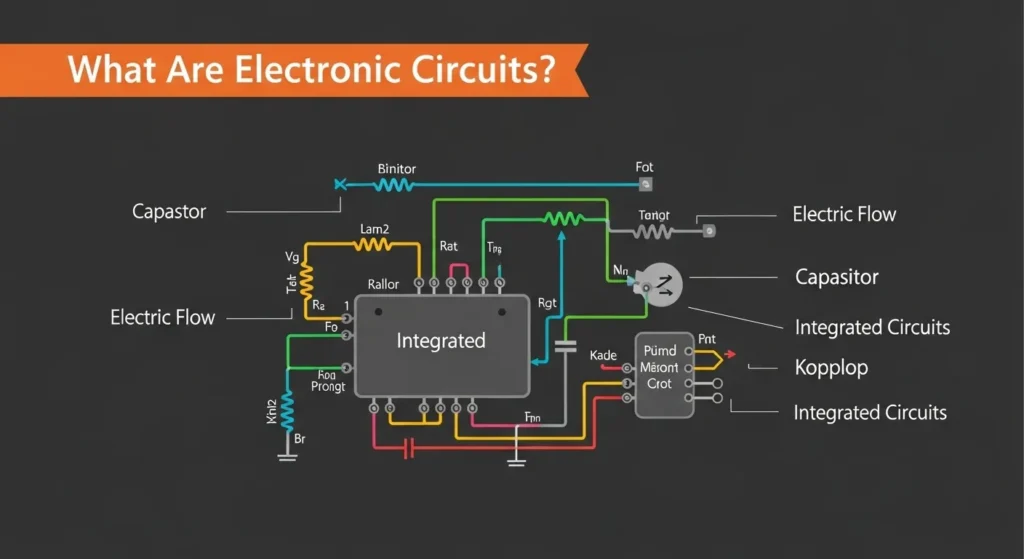
What Are Electronic Circuits? 
Building and Understanding Electronic Circuits for Beginners
Electronics can feel intimidating, but starting with simple electronic circuits is an engaging way. Electronic circuits are essential networks of components such as resistors, capacitors, and integrated circuits (ICs) that manipulate electrical signals to perform specific tasks. An electron device and circuit is a network of components that manipulate electrical signals to perform tasks like lighting LEDs, sounding alarms, or amplifying audio. These electric and circuit systems use components such as resistors in series and parallel, capacitors in series, zener diodes, and IC integrated circuits to achieve functionality. A circuit diagram is a visual blueprint, using standardized symbols to show connections, whether on a breadboard or a printed PCB. For beginners, learning to build simple circuits and understand PCB circuit boards is key to creating reliable electronics circuits. This guide covers these essentials with practical examples, including how to simulate circuits using an electronic circuit simulator.
Essential Electronic Circuit Components
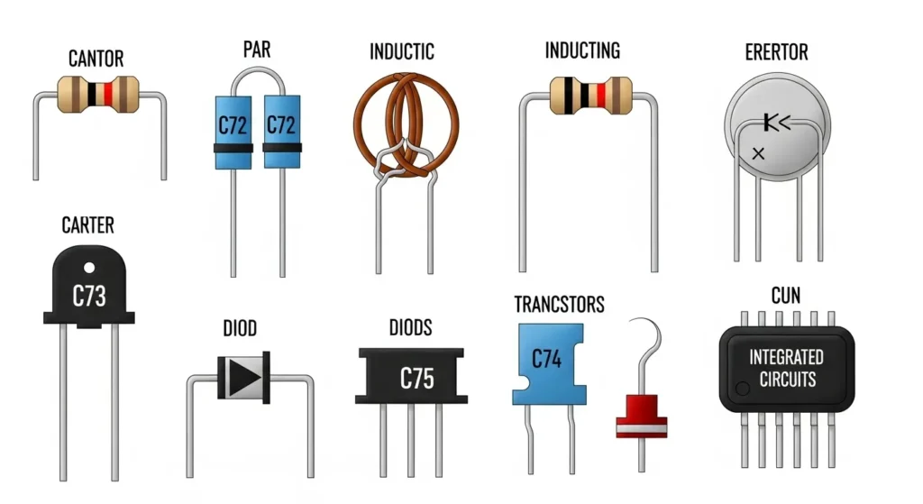
To build electronic circuits, you need to know the core components and their roles in electrical circuits. A resistor controls current flow, shown as a zigzag line, often used in resistors in series to increase resistance or resistors in parallel to divide current, protecting components like LEDs. Capacitors store energy, depicted as parallel lines (curved for polarized types), used in capacitor series for filtering or timing in digital circuits. A zener diode regulates voltage, symbolized as a diode with bent lines at the cathode, ideal for stabilizing circuits. The diode bridge rectifier, a four-diode configuration, converts AC to DC, shown as a diamond of diodes. Transistors, like the BJT NPN transistor, act as switches or amplifiers, with an outward arrow in its symbol, used in circuits like an H-bridge for motor control. Integrated circuits (ICs), such as the op amplifier or 555 timer, combine multiple functions in a chip, represented as a rectangle with pins, perfect for complex tasks. For PCB circuit boards, components are soldered onto a printed PCB designed by a PCB assembly manufacturer. For component details, visit All About Circuits.
Common Electronic Circuit Symbols Chart
In electronics, schematic symbols are the universal language used to represent components in a circuit diagram. Understanding these is crucial for accurately reading blueprints and building functional prototypes.
| Component Name | Symbol Function | Key Identification |
|---|---|---|
| Resistor | Limits current flow and drops voltage. | Zig-zag line (US) or Rectangle (IEC). |
| Capacitor | Stores electrical energy and filters noise. | Two parallel lines (Non-polarized). |
| Diode | Allows current to flow in one direction only. | Triangle pointing to a line. |
| LED | A diode that emits light when powered. | Diode symbol with arrows pointing away. |
| Transistor (NPN) | Acts as a switch or an amplifier. | Circle with three leads; arrow points out. |
| Battery / DC Source | Provides DC electrical energy. | Parallel long and short lines. |
| Ground (GND) | Reference point for zero voltage. | Three horizontal lines of decreasing length. |
Quantitative Principles: Fundamental Circuit Equations
Effective circuit design requires strict adherence to mathematical laws that define voltage, current, and energy consumption. These formulas are the foundation of all electrical analysis.
Core Circuit Laws
- Ohm’s Law: Defines the relationship between Voltage (V), Current (I), and Resistance (R):V=I⋅R
- Power Dissipation (P): The rate at which energy is consumed or converted into heat by a component (critical for safety):P=V⋅I=I2⋅R
- Voltage Gain (Av): The ratio of output voltage to input voltage for an amplifier circuit:Av=VoutVin
Worked Example: Resistor Power Rating
Scenario: Calculate the minimum power rating for a resistor used to drive a 100Ω load from a 12V source.
Calculation: P = V2 R = 122 100 = 144100 = 1.44 Watts Conclusion: To ensure safety and prevent overheating, a 2 Watt (or higher) resistor must be selected, providing a safe margin.
How to Read and Create Simple Circuit Diagrams
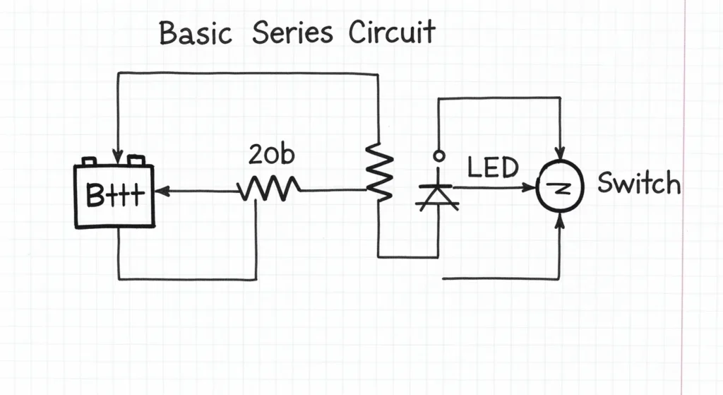
A simple circuit diagram is a roadmap for assembling electronics circuits, using symbols and lines to represent components and connections. Start by identifying the power source, like a battery (long and short lines for positive and negative). Trace connections to understand resistors in series and parallel, capacitor series, or diode bridge rectifier setups. Note polarity for components like zener diodes or IC integrated circuits, and identify the ground (downward triangle). To create a diagram, sketch the power source, add components like a BJT NPN transistor or op amplifier, and ensure logical connections, especially for PCB circuit boards. Tools like Fritzing or an electronic circuit simulator like CircuitLab help design and test circuit diagram examples, streamlining the process for printing circuit boards or prototyping.
Simple Electronic Circuits for Beginners
Below are 13 beginner-friendly electronic projects with detailed simple circuit schematics, components, and instructions, enhanced with keywords like printed PCB, digital circuits, and snap circuits for accessibility.
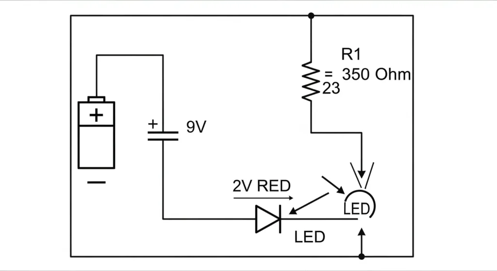
DC Lighting Circuit
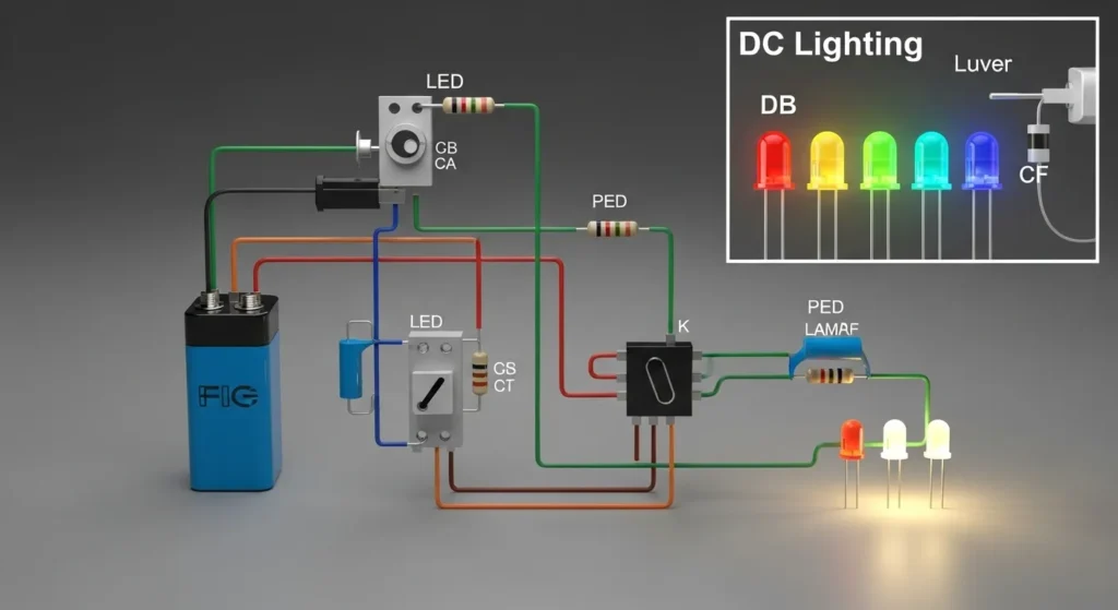
This circuit lights an LED using a DC source, teaching resistors in series. You’ll need an LED, a 330Ω resistor, a 9V battery, a breadboard (or printed PCB for permanence), and wires. Connect the battery’s positive terminal to the resistor, then to the LED’s anode. The cathode connects to ground. The resistor limits current, protecting the LED. Power the circuit to light the LED. For PCB circuit boards, consult a PCB assembly manufacturer for professional assembly PCB. Learn more at Electronics Tutorials.
Rain Alarm
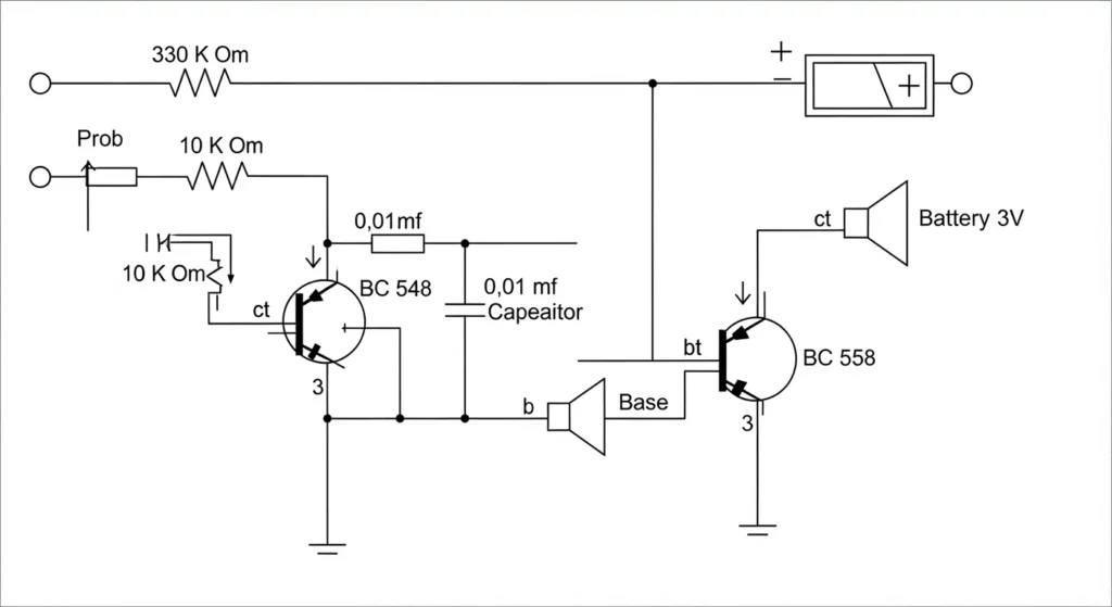
This circuit buzzes when water is detected, using BJT NPN transistors. Gather two BC547 transistors, resistors (1kΩ, 100kΩ), a buzzer, a 9V battery, a water sensor (metal strips), a breadboard (or printed PCB), and wires. Connect the sensor to the first transistor’s base via the 100kΩ resistor. The first transistor’s collector connects to the second transistor’s base. The second transistor’s collector feeds the buzzer, with its other terminal to the positive supply. Ground the emitters. Water triggers the buzzer. Test with water. For transistor circuits, see Homemade Circuit Projects.
Simple Temperature Monitor
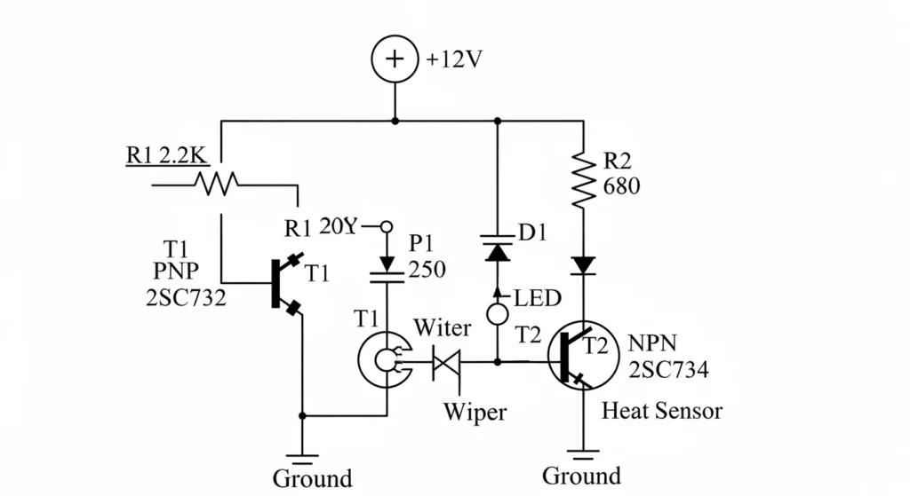
This circuit uses a thermistor and zener diode to monitor temperature. You’ll need an NTC thermistor, a BC547 transistor, an LED, a zener diode (5V), resistors (10kΩ, 330Ω), a 9V battery, a breadboard, and wires. Connect the thermistor to the transistor’s base with a 10kΩ resistor to ground. The zener diode stabilizes voltage across the base. The transistor’s collector connects to the LED via the 330Ω resistor, with the cathode to ground. The emitter goes to ground. Heat reduces thermistor resistance, lighting the LED. Test by warming the thermistor. See Circuit Digest.
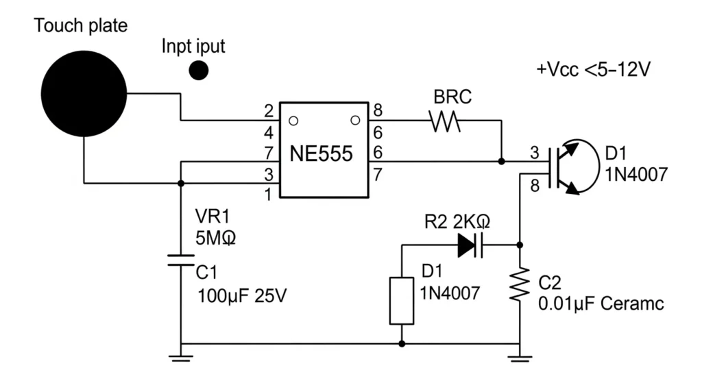
Touch Sensor Circuit
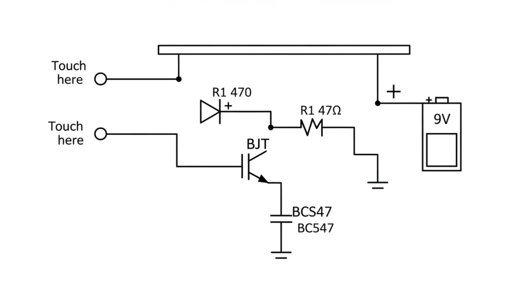
This circuit lights an LED on touch, using a BJT NPN transistor. You’ll need a BC547 transistor, an LED, a 330Ω resistor, touch wires, a 9V battery, a breadboard (or PCB circuit board), and wires. Connect touch wires to the transistor’s base. The collector connects to the LED via the 330Ω resistor, with the cathode to ground. The emitter goes to ground. Touching the wires lights the LED. For snap circuits versions, use modular kits. Explore sensors at Circuits DIY.
Multimeter Circuit
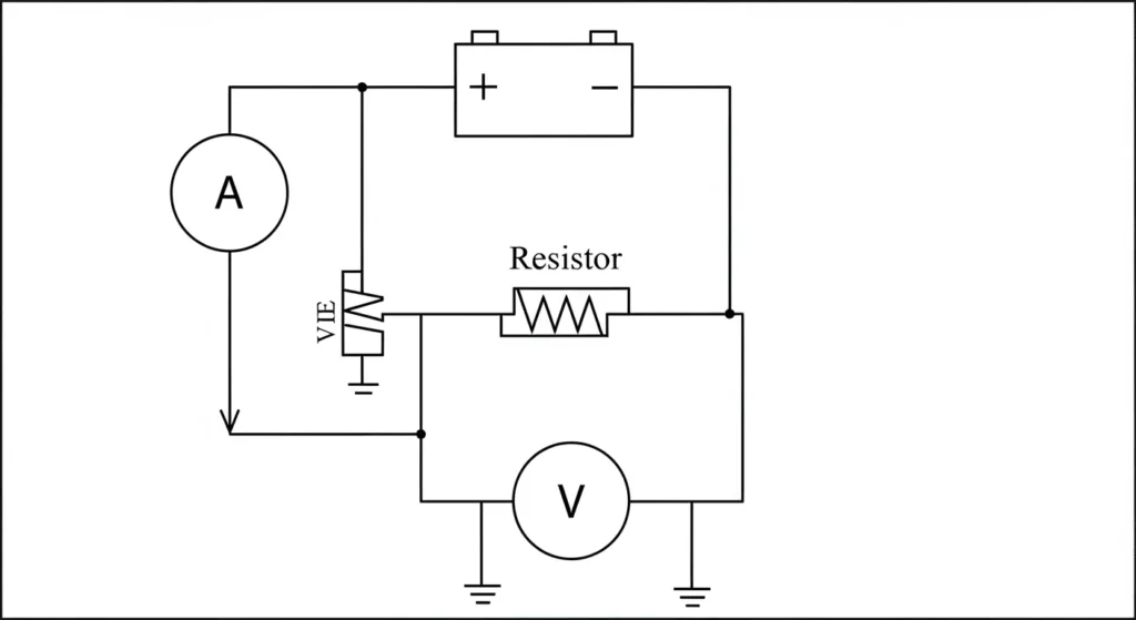
This circuit demonstrates voltage measurement with resistors in series and parallel. You’ll need a voltmeter module, a 9V battery, resistors (1kΩ, 10kΩ), a breadboard, and wires. Create a voltage divider with resistors in series across the battery, then place the 10kΩ resistor in parallel with the voltmeter’s probes. The voltmeter shows the voltage drop. Power the circuit to test. For multimeter tips, see Ladyada’s Multimeter Guide.
LED Flasher Circuit
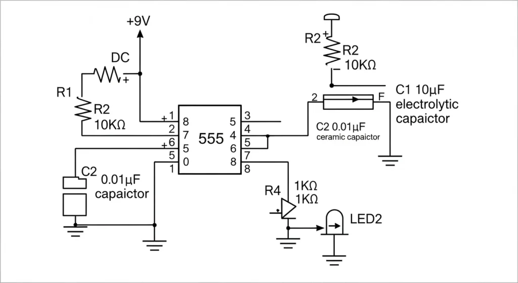
This circuit uses an IC integrated circuit (555 timer) to flash an LED. You’ll need a 555 timer, an LED, resistors (1kΩ, 10kΩ, 330Ω), a 10µF capacitor, a 9V battery, a breadboard, and wires. Connect pin 1 to ground, pin 8 to positive. Link pin 2 to pin 6, with the capacitor to ground. Pin 3 connects to the LED via the 330Ω resistor. Use resistors in series (1kΩ, 10kΩ) between pins 6, 7, and 8 for timing. Power the circuit to flash the LED. Simulate it with an electronic circuit simulator at CircuitLab.
Invisible Burglar Alarm
This circuit uses an LDR and diode bridge rectifier for light detection. You’ll need an LDR, a BC547 transistor, a buzzer, a diode bridge rectifier, resistors (10kΩ, 1kΩ), a 9V battery, a breadboard, and wires. Connect the LDR to the transistor’s base with a 10kΩ resistor to ground. The diode bridge rectifier ensures stable DC. The transistor’s collector connects to the buzzer. Cover the LDR to sound the buzzer. Test in varying light. For LDR circuits, see Electronics For You.
LED Circuit
This circuit uses multiple LEDs with resistors in parallel. You’ll need three LEDs, 330Ω resistors, a 9V battery, a breadboard (or printed PCB), and wires. Connect each LED with its own 330Ω resistor to the positive terminal, with cathodes to ground, forming a parallel circuit. Power the circuit to light all LEDs. For assembly PCB, consult a PCB assembly manufacturer. See SparkFun for parallel circuits.
Simple Light Sensitivity Metronome Using Transistors

This circuit pulses an LED based on light, using BJT NPN transistors. You’ll need two BC547 transistors, an LED, resistors (10kΩ, 1kΩ, 330Ω), an LDR, a 9V battery, a breadboard, and wires. Connect the LDR to the first transistor’s base with a 10kΩ resistor to ground. The first transistor’s collector connects to the second transistor’s base. The second transistor’s collector connects to the LED via the 330Ω resistor. The LED pulses faster in bright light. Test with light changes. See BuildCircuit.
Touch-Based Sensitive Switch Circuit
This circuit toggles an LED with touch, using a Darlington pair and capacitor series. You’ll need two BC547 transistors, an LED, resistors (1MΩ, 330Ω), a 100nF capacitor, touch wires, a 9V battery, a breadboard, and wires. Connect touch wires to the first transistor’s base via the 1MΩ resistor and capacitor. The first transistor’s collector connects to the second transistor’s base. The second transistor’s collector connects to the LED. Touch to toggle the LED. For snap circuits kits, try this design. See Electronics Project.
Practical Applications & Case Studies
Theory is best understood through its application. Electronic circuits are classified by their real-world function:
Rectifiers in Power Supplies
Rectifier circuits, built using diodes (like the diode bridge rectifier), are essential for converting the 120V/240V AC wall power into the DC power required by nearly all electronic devices. These circuits are always followed by smoothing capacitors to remove AC ripple.
Amplifiers in Audio Systems
Circuits utilizing Op Amplifiers (Op-Amps) or BJT transistors are used to boost weak signals without distortion. This is the foundation of high-fidelity audio equipment, where the amplifier’s design determines signal clarity, gain, and frequency response.
Logic Circuits in Microcontrollers
The core of any Microcontroller or IC integrated circuit is the digital logic circuit, composed of billions of microscopic transistors configured as logic gates (AND, OR, NOT). These gates execute the programmed instructions that govern devices like smart thermostats or robotics.
Case Study: Rectifier Circuits in Phone Chargers
A phone charger is fundamentally a rectifier circuit. It first uses a transformer to step down the high AC voltage, then a diode bridge converts the AC to pulsating DC. A large electrolytic smoothing capacitor (across the DC output) reduces ripple, and finally, a voltage regulator (IC) ensures the stable 5V output required for charging your phone battery.
Electronic Eye
This circuit detects light changes, using an LDR and op amplifier. You’ll need an LDR, an LM358 op amplifier, an LED, resistors (10kΩ, 330Ω), a 9V battery, a breadboard, and wires. Connect the LDR to the op amplifier’s inverting input with a 10kΩ resistor to ground. The output connects to the LED via the 330Ω resistor. The LED lights when light hits the LDR. Test in different lighting. For digital circuits, see Circuit Basics.
FM Transmitter Using UPC1651
This circuit transmits audio via FM, using an IC integrated circuit. You’ll need a UPC1651 IC, a microphone, resistors (1kΩ, 10kΩ), capacitors (10pF, 100nF), an antenna, a 9V battery, a breadboard, and wires. Connect the microphone to the UPC1651’s input via the 100nF capacitor. Tune frequency with resistors and capacitors. Connect the antenna to the output. Power and tune an FM radio to hear audio. For printing circuit boards, use a PCB assembly manufacturer. See Electronics Notes.
Automatic Washroom Light
This circuit uses a PIR sensor and H-bridge for motion-activated lighting. You’ll need a PIR sensor, a BC547 transistor, an LED (or relay), resistors (1kΩ, 330Ω), a 9V battery, a breadboard, and wires. Connect the PIR sensor’s output to the transistor’s base via the 1kΩ resistor. The transistor’s collector connects to the LED. Motion triggers the LED. For motor control, adapt with an H-bridge. Test with motion. See Last Minute Engineers.
Comparison of Simple Electronic Circuits
Here’s a comparison of key circuits, including PCB circuit boards and digital circuits, to help you choose:
| Circuit | Complexity | Key Components | Learning Focus |
| DC Lighting Circuit | Low | LED, Resistors in Series | Basic connections, Printed PCB |
| LED Flasher Circuit | Medium | IC Integrated Circuit, LED | Timing, Electronic Circuit Simulator |
| Rain Alarm | Medium | BJT NPN Transistor, Buzzer | Transistor switching, sensors |
| Touch Sensor Circuit | Low | BJT NPN Transistor, LED | Human conductivity, Snap Circuits |
| Automatic Washroom Light | Medium | PIR Sensor, H-Bridge | Motion detection, Digital Circuits |
This table emphasizes electronics circuits suitable for assembly PCB and prototyping.
Series vs Parallel Circuits
| Aspect | Series Connection | Parallel Connection |
|---|---|---|
| Current | Same through all components | Divides among branches |
| Voltage | Divides across components | Same across each branch |
| Total Resistance | Additive (Rtotal=R1+R2+…) | Reciprocal (1/Rtotal=1/R1+1/R2+…) |
| Use Case | Current limiting, LED protection | Power distribution, multiple loads |
Professional Troubleshooting Checklist
Effective diagnosis minimizes downtime and material waste. Use this step-by-step checklist to troubleshoot the most common electronic circuit failures.
Diagnostic Step 1: No Power/Dead Circuit
- Fix: Check Supply Voltage and Continuity. Use a multimeter to confirm the battery or power supply is delivering the correct voltage (VCC). Check continuity between the power rails and ground to ensure no accidental short circuits.
- Tool: Multimeter (Voltage and Continuity Mode).
Diagnostic Step 2: Overheating Components (Smoke/Smell)
- Fix: Verify Resistor Wattage and Transistor Biasing. Overheating is nearly always a power issue. Check if the resistor’s actual power dissipation (calculated using P=I2⋅R) exceeds its rating. For transistors, ensure the biasing (base current) is correct and not forcing excessive collector current.
- Tool: Thermal camera or carefully measured multimeter readings.
Diagnostic Step 3: Noise, Instability, or Erratic Output
- Fix: Add Decoupling Capacitors. Place small ceramic capacitors (e.g., 0.1µF) close to the power pins of all IC integrated circuits (like the 555 timer or Op Amplifiers). This shunts high-frequency noise directly to the ground plane, stabilizing the device.
- Tool: Oscilloscope (to visualize the noise on the power rails).
Industry Standards and Compliance
Professional circuit design is governed by strict international standards that mandate safety, quality, and testing protocols.
Design & Documentation Standards
- IEC 60617 (Graphical Symbols): The international standard used globally for drawing circuit diagrams and schematics, ensuring that symbols for components (like resistors in series or zener diodes) are universally understood.
- IPC Standards (PCB Design): Industry standards (e.g., IPC-2221) defining rules for the physical layout of the printed PCB, including trace widths, clearance, and component placement for manufacturability and reliability.
Safety, Testing, and Compliance
- IEEE Standards: Govern various aspects of electrical testing and safety, ensuring devices perform predictably and reliably across different environments.
- Fuse Ratings and Safety: Every power circuit must include a fuse rated to safely interrupt current flow in case of a short circuit. This is a fundamental safety requirement mandated by global regulations.
- Grounding and ESD Protection: Proper grounding (connecting to a common reference point) is essential for stable operation and safety. ESD (Electrostatic Discharge) protection must be designed into input/output ports to prevent permanent damage to sensitive IC integrated circuits.
Conclusion
Mastering simple electronic circuits is an exciting path to understanding electronics circuits. By learning components like resistors in series and parallel, zener diodes, op amplifiers, and diode bridge rectifiers, and building projects like LED flashers or FM transmitters, you’ll gain practical skills. Use breadboards for prototyping or printed PCBs for durability, and simulate designs with an electronic circuit simulator. These electronic projects for beginners will boost your confidence. Share your creations or ask about repairing circuit boards in the comments—we’re here to help!
About the Author: Dr. Emily is an electrical engineering professor with 12 years of experience in electronic circuit design. She’s passionate about teaching electronics for beginners and digital circuits.
FAQ (Frequently Asked Questions)
Q: What is Ohm’s Law in circuits?
A: Ohm’s Law defines the relationship between voltage (V), current (I), and resistance (R). It is written as V = I × R and is used to calculate current flow, voltage drops, and power dissipation in basic DC circuits.
Q: How do I choose the correct resistor value for an LED?
A: Subtract the LED’s forward voltage from the supply voltage, then divide by the desired LED current using R = (Vsource − Vled) / Iled. Always select the nearest standard resistor value and verify its power rating using P = I² × R to prevent overheating.
Q: What is the difference between series and parallel connections?
A: In a series circuit, components are connected end-to-end, the same current flows through all of them, resistances add up (Rtotal = R1 + R2 + R3), and voltage is divided. In a parallel circuit, all components share the same voltage, current is divided among branches, and total resistance decreases.
Q: Why is ground (GND) important in a circuit?
A: Ground provides a common return path for current and acts as the zero-voltage reference point. Proper grounding is essential for circuit stability, accurate measurements, and reducing electrical noise and interference.
Q: How do you troubleshoot a noisy circuit?
A: The most effective solution is adding decoupling capacitors (typically 0.1µF ceramic) between the power and ground pins of ICs. These capacitors shunt high-frequency noise to ground and stabilize circuit operation.
Q: Why are decoupling capacitors placed close to IC power pins?
A: Placing them close reduces trace inductance, allowing the capacitor to quickly supply transient current and remove noise before it affects the IC, preventing oscillations and instability.
Q: Which standards govern circuit design?
A: Circuit design follows international standards such as IEC 60617 for schematic symbols, IEEE for testing and safety, and IPC standards (like IPC-2221) for PCB layout and manufacturability.
Q: What is the role of an Integrated Circuit (IC) in electronics?
A: An IC combines thousands or millions of transistors, resistors, and capacitors into a single chip, enabling complex functions like signal processing, timing (e.g., 555 timer), control, and computation in a compact and efficient form.
Q: What are real-world applications of amplifiers?
A: Amplifiers are used to increase weak signals in systems such as audio equipment (microphones, speakers) and instrumentation, where tiny sensor signals must be amplified for accurate measurement.
Q: What is a breadboard?
A: A breadboard is a reusable prototyping tool that allows circuits to be built and tested without soldering using internally connected rows of holes.
Q: When should I move from breadboard to PCB?
A: Move to a PCB once the circuit works reliably, noise issues are resolved, and mechanical strength, size, or repeatability becomes important. PCBs offer better reliability and EMI performance.
Q: What is the difference between analog and digital circuits?
A: Analog circuits process continuous signals such as sound or temperature, while digital circuits process discrete values (0s and 1s) used in computers and microcontrollers.
Q: How do you test a circuit with a multimeter?
A: Set the multimeter to voltage, current, or resistance mode, place the probes at the correct test points, and compare the readings with expected values to verify proper operation.
Q: How do you identify the polarity of components?
A: Polarized components must be connected correctly. LEDs usually have a longer leg for the positive (anode), while electrolytic capacitors mark the negative side with a stripe. Reversing polarity can damage components.
Q: What causes a short circuit and how can it be prevented?
A: A short circuit occurs when current flows through an unintended low-resistance path, causing excessive heat. Prevent it by using proper insulation, careful wiring, solder masks, and fuses.
Q: What tools does a beginner need for electronics?
A: Essential tools include a digital multimeter, breadboard, soldering iron, basic hand tools, and a variable DC power supply for safe testing and development.