What Is a Capacitor? Complete Guide: Types, Formula, Applications & How It Works
From basic charge storage to advanced filter circuits everything an engineer and student needs to know about capacitors in one place.
🎯 Key Takeaways
- ✅ A capacitor stores electrical energy in an electric field between two conductive plates separated by a dielectric (insulator)
- ✅ Capacitance is measured in Farads (F) most real components are in µF (microfarads) or pF (picofarads)
- ✅ Core formula: Q = C × V charge equals capacitance times voltage
- ✅ Capacitors block DC current but pass AC current this is their most important circuit behavior
- ✅ The 10 main types differ by dielectric material: ceramic, electrolytic, tantalum, film, mica, supercapacitor, and more
- ✅ Applications range from power supply filtering to touchscreens, camera flashes, DRAM memory, and energy recovery in EVs
What Every Engineer Should Know About Capacitors
A fully charged capacitor stops DC current completely. But AC passes through because the alternating voltage continuously charges and discharges the plates.
Electrolytic and tantalum capacitors are polarized connect them backwards and they can overheat, leak, or explode. Always check the negative stripe or longer lead.
Energy stored = ½CV². Doubling voltage quadruples stored energy. This is why high-voltage capacitors in camera flashes store enough energy to cause injury.
Always place a 100nF ceramic capacitor across VCC and GND of every IC. It suppresses voltage spikes from switching transients the single most common PCB fix.
τ = RC. After one time constant, a capacitor charges to 63.2% of supply voltage. After 5τ, it is considered fully charged (99.3%). Critical for timer and filter design.
Supercapacitors charge in seconds and last millions of cycles, but store far less energy per gram than batteries. Best for short-burst high-power applications like regenerative braking.
What Is a Capacitor? (60-Second Answer)
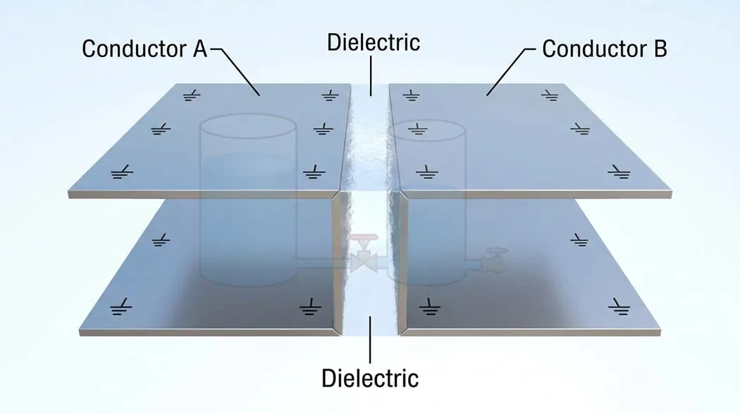
A capacitor is a passive electronic component that stores electrical energy in an electric field. It consists of two conductive plates separated by an insulating material called a dielectric. When voltage is applied, positive charge builds on one plate and negative charge on the other storing energy without any chemical reaction, unlike a battery.
The key difference from a battery: a capacitor releases all its stored energy almost instantly (in microseconds), while a battery releases energy slowly over hours. This makes capacitors ideal for filtering, timing, coupling, and any application requiring rapid charge and discharge.
📋 Table of Contents
- How Does a Capacitor Work? (Physics Explained)
- Core Capacitor Formulas Every Engineer Must Know
- 10 Types of Capacitors Complete Comparison
- Core Functions: What Does a Capacitor Actually Do in a Circuit?
- Real-World Applications From Smartphones to EVs
- Pros and Cons of Capacitors
- How to Choose the Right Capacitor
- Capacitors in Series and Parallel
- Capacitor FAQ
How Does a Capacitor Work?
At its core, a capacitor is deceptively simple: two conductive plates facing each other, separated by a non-conducting material (the dielectric). When you connect a voltage source, electrons accumulate on one plate (making it negative) and are pulled away from the other plate (making it positive). This separation of charges creates an electric field between the plates and that electric field is where the energy lives.
The Charging and Discharging Process
When you connect a capacitor to a DC voltage source, current flows and charges build up on the plates. As charge builds, the voltage across the capacitor rises. Eventually, it matches the supply voltage at which point no more current flows and the capacitor is fully charged. Disconnect the source, and the capacitor holds that charge (in an ideal world, forever in practice, there is always some leakage).
When you connect a charged capacitor to a load (like a resistor or LED), it discharges releasing its stored energy. The rate of discharge depends on the RC time constant: τ = R × C.
The first time I truly understood capacitors was not in a lecture it was when I accidentally touched the leads of a charged 450V electrolytic capacitor on a CRT monitor power supply. The discharge left a burn mark on my screwdriver and a lesson I never forgot: capacitors store energy even when the power is off. Large capacitors in power supplies can hold lethal charge for minutes or hours after disconnection. Always discharge them through a resistor before working near them.
Why the Dielectric Matters
The dielectric is not just an insulator it actively increases capacitance. When the electric field is applied, the dielectric material becomes polarized: its molecules align with the field, effectively reducing the field strength and allowing more charge to accumulate on the plates for the same voltage. This effect is captured by the dielectric constant (relative permittivity, εᵣ):
A = plate area (m²) | d = separation between plates (m)
This formula explains everything about how capacitors are designed: increase plate area (A), use a high-εᵣ dielectric, or decrease plate separation (d) capacitance increases. This is why ceramic capacitors with high-εᵣ materials (εᵣ up to 10,000) can pack large capacitance into tiny packages.
Core Capacitor Formulas Every Engineer Must Know
These 6 formulas govern virtually all capacitor behavior in circuit design. Understanding them turns a confusing component into a predictable and powerful tool.
Example: A 100µF capacitor at 12V stores Q = 100×10⁻⁶ × 12 = 0.0012 Coulombs (1.2 mC)
Example: 100µF at 400V → E = ½ × 100×10⁻⁶ × 400² = 8 Joules (enough to cause serious injury)
Example: R=10kΩ, C=100µF → τ = 10,000 × 0.0001 = 1 second
This exponential curve not linear is why RC circuits are used in timing applications
Higher frequency → lower Xc → capacitor passes signal more easily. This is why capacitors filter high-frequency noise.
Parallel: increases capacitance. Series: increases voltage rating (each capacitor shares the voltage)
A common RC low-pass filter uses a resistor and capacitor to pass low frequencies and block high frequencies. The cutoff frequency (f_c) where the output drops to 70.7% of input is:
f_c = 1 / (2π × R × C)
For R = 10kΩ and C = 10nF: f_c = 1 / (2π × 10,000 × 10×10⁻⁹) = 1,592 Hz. Frequencies above 1,592 Hz are attenuated. This is the fundamental circuit behind audio tone controls, anti-aliasing filters, and power supply ripple rejection.
10 Types of Capacitors Complete Comparison
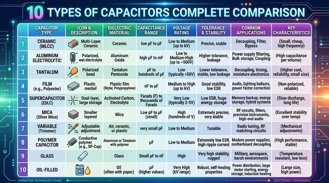
The dielectric material determines almost everything about a capacitor’s performance: its value range, voltage rating, temperature stability, polarity requirement, physical size, and cost. Here are all 10 major types:
The most widely used capacitor in electronics. Made from ceramic material as the dielectric, coated with silver electrodes. Available in Class 1 (C0G/NP0 very stable) and Class 2 (X5R, X7R, Y5V higher capacitance, less stable).
Best for: Decoupling/bypass (100nF across IC power pins), high-frequency filtering, timing circuits, RF applications. The go-to choice for 90% of small-signal work.
X7R and Y5V ceramics lose significant capacitance under DC bias voltage. A 10µF X5R capacitor rated at 10V may only provide 2–3µF at its rated voltage. Always check the capacitance vs. voltage curve in the datasheet for Class 2 ceramics in critical designs.
Uses an aluminum oxide film grown on an aluminum foil anode as the dielectric, with a liquid or solid electrolyte as the cathode. Offers very high capacitance in a relatively small volume, but is polarized and has limited lifespan (electrolyte dries out over time typically 1,000–10,000 hours at rated temperature).
Best for: Power supply bulk filtering, audio amplifier coupling, DC-DC converter output filtering. The classic capacitor in every power supply “can” on a PCB.
Uses tantalum pentoxide as the dielectric. Smaller and more stable than aluminum electrolytics with better frequency characteristics and longer lifespan. However, they are more expensive and critically they can fail catastrophically (catch fire or explode) if reverse-biased or subjected to voltage spikes above rating.
Best for: Portable electronics, medical devices, military/aerospace, anywhere that needs small size and high reliability with stable capacitance.
Never exceed the voltage rating not even briefly. Always use a tantalum with a voltage rating at least 2× the maximum circuit voltage (derating). A reverse-connected or over-voltage tantalum can ignite and burn intensely. They are banned in some aerospace applications for this reason.
Uses a thin plastic film (polyester/mylar or polypropylene) as the dielectric. Excellent stability, very low leakage, no polarity restriction, and self-healing capability (a local breakdown burns away rather than causing permanent failure). The preferred choice for precision and audio circuits.
Best for: Audio crossover networks, motor run/start capacitors, switching power supply snubbers, precision timing, high-voltage AC circuits. Audiophiles swear by polypropylene film capacitors for their low distortion.
Uses natural or synthetic mica as the dielectric. Extremely stable over temperature and frequency, very low loss, and high accuracy. Expensive and limited to small capacitance values, but unmatched in RF and high-precision applications.
Best for: RF transmitters and receivers, oscillator circuits, high-frequency filters, radar systems, anywhere requiring precise and stable small capacitance values.
Electrochemical Double Layer Capacitors (EDLC) store energy at the interface between a liquid electrolyte and a high-surface-area carbon electrode (activated carbon). Capacitance can reach thousands of Farads. They bridge the gap between conventional capacitors and batteries more energy than capacitors, more power than batteries.
Best for: Regenerative braking in EVs, UPS backup, solar energy storage, smart meters with battery backup, burst-power applications (camera flashes at scale).
All 10 Types Quick Reference Comparison
| Type | Capacitance Range | Voltage Range | Polarized? | Key Strength | Key Weakness |
|---|---|---|---|---|---|
| Ceramic (C0G/NP0) | 1 pF–1 nF | up to 5kV | No | Ultra stable, low loss | Small values only |
| Ceramic (X7R/X5R) | 1 nF–100 µF | 6.3V–100V | No | Small, cheap, versatile | Capacitance drops under DC bias |
| Aluminum Electrolytic | 1 µF–100,000 µF | 6.3V–500V | Yes | Very high capacitance, cheap | Limited lifespan, leakage |
| Tantalum | 0.1 µF–2,200 µF | 4V–50V | Yes | Compact, stable, low ESR | Can ignite if misused |
| Polyester Film | 1 nF–10 µF | 50V–630V | No | Stable, self-healing | Larger size than ceramic |
| Polypropylene Film | 100 pF–100 µF | 63V–2kV | No | Very low distortion, audio grade | Large, expensive |
| Silver Mica | 1 pF–10,000 pF | 100V–500V | No | Ultra precise, RF stable | Expensive, small values only |
| Supercapacitor (EDLC) | 0.1 F–12,000 F | 2.5V–5V | Yes | Millions of cycles, fast charge | Low voltage, low energy density |
| Polymer Capacitor | 10 µF–1,500 µF | 2V–100V | Yes | Very low ESR, no electrolyte dry-out | More expensive than aluminum |
| Variable Capacitor (Tuning) | 5 pF–500 pF | Up to kV | No | Adjustable capacitance | Mechanical, limited to radio/RF |
Core Functions: What Does a Capacitor Actually Do in a Circuit?
A capacitor’s behavior changes depending on how it is connected. These are the 6 fundamental functions you will encounter in every field of electronics:
① Filtering (Smoothing Power Supply Ripple)
The most common use. After a rectifier converts AC to DC, the output still contains ripple small voltage fluctuations at the AC frequency. A large electrolytic capacitor placed across the output acts as a reservoir: it charges during voltage peaks and discharges during troughs, smoothing the output into a near-constant DC voltage.
For a 50Hz mains-derived supply with 1A load current and 1V acceptable ripple: C = I / (2 × f × ΔV) = 1 / (2 × 50 × 1) = 10,000 µF. This is why large power supplies contain massive cylindrical electrolytic capacitors.
② Decoupling (Bypass Capacitor)
Digital ICs switch millions of times per second, drawing brief high-current spikes from the power rail. These spikes cause voltage transients that can corrupt nearby logic. A 100nF ceramic capacitor placed directly between VCC and GND of every IC provides a local charge reservoir it supplies the transient current locally before the power supply can respond. This is the single most important rule in PCB design.
③ Coupling (AC Signal Coupling)
A capacitor blocks DC but passes AC. In audio amplifiers, a coupling capacitor between stages passes the audio signal (AC) while blocking the DC bias voltage of the previous stage from affecting the next. This allows each amplifier stage to operate at its own independent DC operating point.
④ Timing (RC Circuits)
Because a capacitor charges at a predictable exponential rate (τ = RC), it forms the basis of timing circuits. The classic 555 timer uses an RC circuit to determine its output frequency. Timing capacitors must be stable (C0G ceramic or film) temperature-unstable capacitors cause timing drift.
⑤ Energy Storage (Flash / Pulse Power)
A capacitor can release all its stored energy nearly instantaneously much faster than a battery. Camera flashes use a capacitor charged to 300–400V. When the shutter fires, the capacitor discharges through the flash tube in microseconds, producing thousands of watts of light power for a brief moment.
⑥ Sensor (Touchscreens, Microphones, Pressure Sensors)
A capacitor’s value changes when the distance between its plates changes or when a conductor approaches. Touchscreens use a grid of capacitors your finger (a conductor) changes the capacitance at the point of contact, and the controller detects the position. Condenser microphones use a moving diaphragm as one plate of a capacitor sound waves move the diaphragm, changing capacitance and generating a signal.
Real-World Applications From Smartphones to EVs
Capacitors appear in virtually every electronic device ever made. Here is where they actually live and what they do:
| Application | Capacitor Type | Capacitor Function | Typical Value |
|---|---|---|---|
| Smartphone touchscreen | Projected capacitance array | Detects finger position via capacitance change | pF range |
| DRAM memory cell | MOS capacitor (on-chip) | Stores 1 bit as charge (1 = charged, 0 = discharged) | ~30 fF |
| Power supply (mains adapter) | Aluminum electrolytic | Filters rectified AC into smooth DC | 1,000–10,000 µF |
| Camera flash | Aluminum electrolytic (HV) | Stores energy, discharges in microseconds | 100–1,000 µF at 300V |
| PCB (every IC) | Ceramic (X7R/C0G) | Decoupling suppresses switching noise | 100nF |
| Audio amplifier | Film / polymer electrolytic | Signal coupling between stages, tone filtering | 1 µF–100 µF |
| AC motor starter | Film / oil-filled | Creates phase shift to start single-phase motors | 4–100 µF at 250–450V AC |
| Electric vehicle (EV) inverter | Film (DC link capacitor) | Smooths DC bus, absorbs switching transients | 500–2,000 µF at 400–800V |
| Regenerative braking (EVs/trains) | Supercapacitor bank | Captures braking energy, releases for acceleration | Hundreds of Farads |
| Radio / RF tuner | Variable / mica | Tunes resonant frequency of LC circuit | 10–500 pF |
| Power factor correction | Film (AC rated) | Compensates inductive load, reduces reactive power | 10–1,000 µF at 400–690V AC |
| Microcontroller timer (555, Arduino) | Ceramic or film | Sets delay or oscillation frequency via RC | 1 nF–100 µF |
In EV inverter design, the DC link capacitor is one of the most critical and expensive components. We were working on a 150kW traction inverter, and the film capacitor bank alone cost more than all the IGBTs combined. The capacitor had to handle 700V DC with 200A RMS ripple current at switching frequencies of 10kHz, all while maintaining performance from −40°C to +85°C. Choosing the right capacitor was a six-week engineering exercise involving dozens of trade-off decisions. That experience permanently changed how I teach capacitor selection.
Pros and Cons of Capacitors
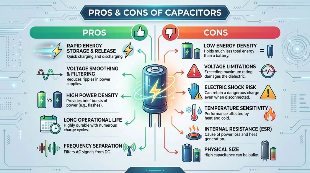
Understanding both strengths and limitations is essential for making good design decisions. No component is perfect for every situation.
✅ Advantages
- Instant energy release: Discharge rate far exceeds batteries ideal for pulse and flash applications
- Extremely long lifespan: Ceramic and film capacitors last decades with no degradation; supercapacitors handle millions of charge cycles
- Wide temperature range: C0G ceramics operate from −55°C to +125°C without significant change
- No chemical reaction: Unlike batteries, capacitors don’t involve chemical reactions no risk of toxic leakage (except electrolytic electrolyte)
- Passive, no power required: Capacitors store energy with zero quiescent power consumption
- AC signal control: Uniquely able to block DC while passing AC enables coupling, filtering, and impedance matching
- Tiny and cheap: A 100nF ceramic capacitor costs less than $0.01 in quantity and is smaller than a grain of rice
- Self-healing (film): Metallized film capacitors recover from local dielectric breakdowns automatically
❌ Disadvantages
- Low energy density: Even supercapacitors store ~30× less energy per gram than lithium-ion batteries
- Polarity sensitivity: Electrolytic and tantalum types will fail dangerously if reverse-connected
- Capacitance tolerance: Cheap ceramic capacitors can have ±20% tolerance poor for precision timing
- Voltage-dependent capacitance: Class 2 ceramics (X7R, Y5V) lose 50–80% of capacitance near rated voltage
- Electrolytic lifespan: Aluminum electrolytics dry out over time, especially at high temperatures the #1 cause of power supply failure
- ESR (Equivalent Series Resistance): High ESR causes power loss and heating in switching applications
- Safety hazard when charged: High-voltage capacitors store lethal energy and can remain dangerous long after power is removed
- Frequency limitations: Large electrolytics are only effective at low frequencies their internal inductance makes them ineffective at RF
How to Choose the Right Capacitor
Selecting the wrong capacitor is one of the most common causes of circuit failure in professional designs. Here is the systematic approach engineers use:
| Design Requirement | What to Check | Rule of Thumb |
|---|---|---|
| Capacitance value | Circuit requirement (timing, filter cutoff, energy) | Calculate from formula; use nearest standard E12/E24 value |
| Voltage rating | Maximum voltage in circuit + transients | Use at least 2× the maximum operating voltage (derating) |
| Polarity | Is the capacitor used in a DC or AC circuit? | Only polarized caps in DC circuits with known voltage polarity |
| Temperature range | Operating environment min/max temperature | C0G for stable; X7R for general; Y5V only for non-critical bypass |
| Frequency | Signal frequency or switching frequency | Ceramic for RF/high-freq; electrolytic only for low-freq (<1kHz) |
| ESR requirement | Switching regulator output, high ripple current | Low ESR polymer or tantalum; check ripple current rating |
| Size constraint | PCB footprint available | SMD ceramic first; through-hole electrolytic for large values |
| Precision required | Timing circuits, filters with tight tolerance | C0G (NPO) ceramic ±5% or better; avoid Y5V for any precision |
Engineer’s Quick-Select Guide
Decoupling (any digital IC): 100nF X7R ceramic, 0402 or 0603 SMD, as close to IC power pin as possible.
Bulk power supply filter: 470µF–10,000µF aluminum electrolytic, voltage rating ≥ 2× DC rail.
Precision timing (555, oscillator): C0G/NP0 ceramic or film never X7R or electrolytic.
Audio coupling: Film or polymer electrolytic avoid cheap aluminum electrolytic for critical audio paths.
High-voltage snubber: Film capacitor rated for AC voltage never electrolytic across mains.
Capacitors in Series and Parallel
Capacitors combine opposite to resistors a fact that confuses many beginners. Here is the full picture:
Capacitors in Parallel Capacitances Add
When capacitors are connected in parallel (all positive terminals together, all negative terminals together), the total capacitance is the sum of all individual capacitances:
Example: Three 100µF capacitors in parallel → 300µF total. Same voltage rating as the lowest-rated individual capacitor.
Why use parallel capacitors? Different capacitor types excel at different frequencies. In power supply filtering, engineers use a 1000µF electrolytic (handles low-frequency ripple) in parallel with a 100nF ceramic (handles high-frequency switching noise). Each type handles its optimal frequency range.
Capacitors in Series Capacitance Reduces, Voltage Splits
In series, capacitances combine like resistors in parallel:
Example: Two 100µF / 25V capacitors in series → 50µF total, but rated for 50V. Useful when you need a higher voltage rating than a single capacitor provides.
When connecting polarized capacitors in series for higher voltage operation, each capacitor may not share the voltage equally due to tolerance differences in leakage current. Always add balancing resistors (typically 100kΩ) across each capacitor to ensure equal voltage sharing in DC circuits.
❓ Capacitor FAQ
Not for most applications. Capacitors store energy, but their energy density is vastly lower than batteries even a supercapacitor stores roughly 30× less energy per gram than a lithium-ion cell. A capacitor also discharges its voltage as it releases energy (voltage drops proportionally to remaining charge), while a battery maintains roughly constant voltage through most of its discharge. Capacitors excel at applications requiring fast charge/discharge cycles, very long cycle life, and instantaneous power delivery not sustained energy supply. The exception: some specialized backup circuits use small supercapacitors to hold a microcontroller in operation for seconds to minutes during brief power interruptions.
For non-polarized capacitors (ceramic, film, mica) nothing. They work in either direction. For polarized capacitors (aluminum electrolytic, tantalum, polymer electrolytic): the reverse voltage breaks down the oxide dielectric layer. Aluminum electrolytics will heat up, release gas, and eventually rupture the pressure vent or explode. Tantalum capacitors can catch fire within seconds of reverse connection or even slightly exceed their rated voltage. Always identify the negative stripe or the longer positive lead before installing a polarized capacitor.
This is often due to replacing electrolytic capacitors with the wrong type. Key mistakes: using a lower voltage rating than the original, installing modern low-ESR capacitors in circuits designed for higher-ESR types (some older amplifier circuits were tuned for specific ESR values), using the wrong capacitance value (especially in timing or feedback circuits), or failing to replace capacitors in matched pairs in differential circuits. Another common cause: the new capacitors are fine, but the original failure damaged other components (transistors, diodes) that weren’t replaced.
ESR (Equivalent Series Resistance) is the resistance a capacitor appears to have in series with itself at AC frequencies it’s not a physical resistor but results from lead resistance, contact resistance, and dielectric losses. High ESR causes power dissipation (P = I² × ESR) inside the capacitor, which generates heat and voltage drop. In switching power supplies, a capacitor with 1Ω ESR carrying 2A ripple current wastes 4W as heat that will fail quickly. Low-ESR polymer or low-ESR electrolytic capacitors are mandatory in switching regulators. Datasheets list ESR in milliohms; always check it for any high-current application.
Modern smartphones use projected capacitive touchscreens. A transparent conductive grid (typically indium tin oxide) forms rows and columns of electrodes, creating tiny capacitors at each intersection. The controller measures capacitance at every grid point. When your finger (a conductor with its own capacitance) approaches the screen, it distorts the electric field and measurably changes the capacitance at nearby intersection points. By measuring how much each grid point changes, the controller calculates your finger’s exact X-Y position to sub-millimeter accuracy, even through glass. Multi-touch works because the system simultaneously monitors all grid points multiple distinct distortions = multiple fingers.
Small capacitors (under 50V, under 100µF) can be discharged by briefly connecting their terminals through a 1kΩ resistor this limits discharge current to a safe level. Large capacitors (power supply electrolytics, CRT monitor capacitors, camera flash capacitors) should be discharged through a resistor rated to handle the power: for a 450V/1000µF capacitor, use a 10kΩ 5W resistor, hold it across the terminals for at least 30 seconds, then verify with a voltmeter before touching. Never short large capacitors directly the discharge current can be thousands of amperes for milliseconds, destroying the capacitor and causing injury. Always treat a capacitor-containing circuit as live until you have personally verified the voltage with a meter.
🎯 The Bottom Line
Capacitors are arguably the most versatile passive components in all of electronics. The same principle two plates, a dielectric, an electric field gives us the smooth DC power rail in your laptop, the precise timing in your microcontroller, the snap of a camera flash, the responsiveness of a touchscreen, and the regenerative braking system in an electric vehicle.
Understanding capacitors at the formula level (Q=CV, E=½CV², τ=RC, Xc=1/2πfC) transforms them from mysterious cylinders on a PCB into predictable, designable tools. The choice of dielectric material dictates nearly everything else: stability, size, polarity, voltage handling, frequency range, and lifespan.
Start with these three: a 100nF ceramic for decoupling, a 10µF electrolytic for bulk filtering, and a 100pF C0G ceramic for precision timing. Master those three applications and you’ll have covered 80% of what capacitors do in real circuits.
⚠️ Safety Notes
- High-voltage capacitors (above 50V) can hold lethal charge long after power is removed. Always discharge through a resistor and verify with a voltmeter before touching.
- Aluminum electrolytic and tantalum capacitors will fail and potentially explode or ignite if reverse-connected or subjected to voltage above their rating.
- Never connect a non-AC-rated capacitor across mains voltage (120V/240V AC). Use only X-rated or Y-rated capacitors specifically designed for mains connection.
- Formulas and typical values given in this guide are for educational reference. Always verify against manufacturer datasheets for any real design application.
📚 Continue Learning on Procirel
📎 Sources & References
- 1Kemet Corporation Capacitor Technology Overview Dielectric materials, type selection, and application notes [Industry Reference]
- 2Murata Manufacturing Ceramic Capacitor Application Notes DC bias characteristics, temperature coefficients, Class 1 vs Class 2 [Manufacturer]
- 3IEC 60384-1 Fixed Capacitors for Use in Electronic Equipment General performance standards and test methods [Standard]
- 4Vishay Tantalum Capacitor Application Guide Voltage derating, failure modes, safety guidelines [Manufacturer]
- 5Panasonic Industrial Electrolytic Capacitor Lifetime Estimation Temperature vs. lifespan data, ripple current ratings [Manufacturer]
- 6Maxwell Technologies (Tesla subsidiary) Supercapacitor Application Guide EDLC energy density, cycle life, EV applications [Industry Reference]
- 7Texas Instruments Capacitor Selection for Power Supplies ESR requirements, filter design, decoupling strategy [Application Note]
- 8Sedra & Smith Microelectronic Circuits, 8th Edition Theoretical basis for capacitor behavior in analog and digital circuits [Academic Textbook]