[latexpage]
Voltage Divider: Understanding and Using This Essential Circuit
I remember the first time I stumbled across a voltage divider in my electronics class. It was one of those moments where a simple concept clicked, and suddenly, a whole world of circuit design opened up. A voltage divider is one of the most fundamental tools in electronics, elegant in its simplicity yet powerful in its applications. Whether you’re a hobbyist tinkering with an Arduino or an engineer designing complex systems, understanding the voltage high dividers is a must. In this guide, I’ll walk you through what a voltage divider is, how it works, its formula, practical uses, and even some advanced considerations. Let’s dive into the world of circuits with a friendly, hands-on approach, exploring the technical details while keeping things clear and approachable.
What Is a Voltage Divider, and Why Does It Matter?
Imagine you’re building a small project, maybe a sensor circuit for a home automation system. You’ve got a 9V battery, but your sensor needs 3V to operate safely. How do you make that happen without frying your components? Enter the voltage divider a simple circuit that takes an input voltage and splits it into smaller, usable voltages. At its core, a voltage divider uses two resistors in series to create a specific output voltage that’s a fraction of the input. It’s like slicing a pizza into portions: you decide how much each part gets based on the size of the slice.
The beauty of a voltage divider lies in its versatility. From powering sensors to setting reference voltages in amplifiers, this circuit is everywhere. It’s a building block for more complex designs, like those found in an Nvidia Jetson Nano project or a high-voltage system. But before we get too far, let’s break down the basics to ensure we’re all on the same page.
The Voltage Divider Formula: The Heart of the Circuit


To understand how a voltage divider works, you need to know its formula. Picture two resistors, R1 and R2, connected in series across a power source with voltage Vin. The output voltage, Vout, is taken across R2. The divider equation is:
Vout = Vin × (R2 / (R1 + R2))
This formula comes from Ohm’s law, which tells us how voltage, current, and resistance relate. In a series circuit, the total resistance is the sum of R1 and R2, and the current flowing through both resistors is the same. The voltage across each resistor depends on its resistance value. By choosing the right resistors, you can get the exact output voltage you need.
Let’s say you have a 12V battery, and you want 4V for a component. If R1 is 8kΩ and R2 is 4kΩ, the total resistance is 12kΩ. Plugging into the divider formula:
Vout = 12V × (4kΩ / (8kΩ + 4kΩ)) = 12V × (4/12) = 4V
It’s straightforward, but the magic happens when you start playing with resistor values to fine-tune your circuit.
Building a Voltage Divider: A Step-by-Step Example


Let’s walk through a real-world scenario. Suppose you’re working on a project with an Nvidia Jetson Nano, a compact computer that needs precise voltage levels for its sensors. You’re using a 5V power supply, but one of your sensors requires 2V. Here’s how you’d set up a voltage divider.
First, choose two resistors. For simplicity, let’s pick R1 = 3kΩ and R2 = 2kΩ. Connect them in series: one end of R1 to the 5V supply, the other end of R1 to one end of R2, and the other end of R2 to ground. Your output voltage is measured across R2. Using the voltage divider equation:
Vout = 5V × (2kΩ / (3kΩ + 2kΩ)) = 5V × (2/5) = 2V
You’ve got your 2V! But here’s where it gets practical: always double-check your resistor values with a multimeter, as real-world resistors have tolerances (usually ±5% or ±10%). A slight variation can shift your output voltage, which might matter in sensitive circuits.
Why Ohm’s Law Is Your Best Friend Here

The voltage divider formula isn’t some standalone magic—it’s rooted in Ohm’s law: V = I × R. In a series circuit, the current is constant, so the voltage across each resistor depends on its resistance. This is why the voltage divider equation works: it’s just ohms law calculator rearranged to solve for the voltage across R2.
To make this concrete, consider the current in our previous example. The total resistance is 5kΩ, and the input voltage is 5V. The current is:
I = Vin / (R1 + R2) = 5V / 5kΩ = 1mA
The voltage across R2 is then:
Vout = I × R2 = 1mA × 2kΩ = 2V
This confirms our earlier calculation and shows how Ohm’s law underpins the voltage divider. If you’re ever stuck, an Ohm’s law calculator can help you verify your math, but understanding the relationship is key.
Practical Applications: Where Voltage Dividers Shine
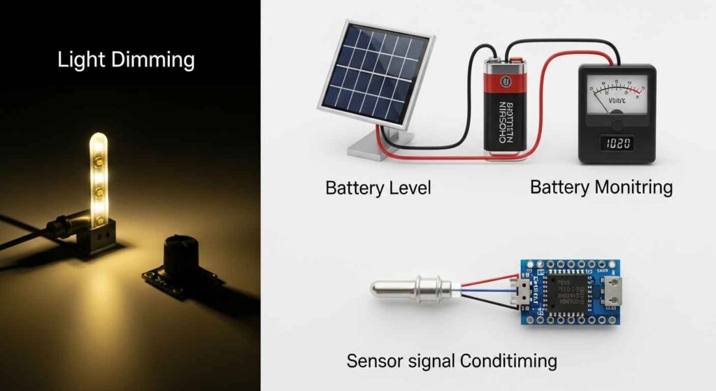
Voltage dividers are everywhere in electronics. When I was building a temperature sensor circuit for a greenhouse, I used a voltage divider to scale down a 9V supply to 3.3V for a microcontroller. This is a common use case: microcontrollers like those in the Jetson Nano often need specific voltage levels to avoid damage.
Another place you’ll see voltage dividers is in audio circuits. They’re used to set bias points in amplifiers, ensuring the signal stays within the right range. In high-voltage systems, like those in industrial equipment, voltage dividers scale down signals for safe monitoring. Even in simple projects, like adjusting the brightness of an LED, a voltage divider can help control the voltage across the circuit.
But it’s not just about splitting voltages. Voltage dividers are often paired with other components, like capacitors or transistors, to create filters or reference voltages. They’re a foundational piece of the electrical wiring & circuit puzzle, making them indispensable for anyone working with electronics.
Current Divider vs. Voltage Divider: What’s the Difference?
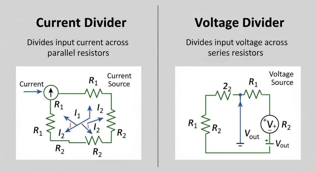
While we’re on the topic, let’s clear up a common confusion: the difference between a voltage divider and a current divider. A voltage divider splits voltage across resistors in series, as we’ve discussed. A current divider, on the other hand, splits current across resistors in parallel. The current divider rule formula is:
Iout = Itotal × (Rtotal / Rbranch)
where Rtotal is the equivalent resistance of the parallel resistors, and Rbranch is the resistance of the branch you’re measuring. For example, if you have two resistors in parallel, R1 and R2, the current through R2 is:
I2 = Itotal × (R1 / (R1 + R2))
This is useful in circuits where you need to control how much current flows through different paths, like in a circuit breaker circuit or a wiring connection diagram for a complex system. Understanding both dividers helps you design more efficient circuits.
Limitations and Pitfalls: What to Watch Out For

Voltage dividers are fantastic, but they’re not perfect. One major limitation is that they’re sensitive to load. If you connect a load (like a sensor or another circuit) across R2, it acts like a parallel resistor, changing the effective resistance and thus the output voltage. This is called voltage drop, and it can throw off your calculations.
For example, let’s say you designed a voltage divider for 3V, but the load you connect has a resistance of 1kΩ. This load parallels R2, reducing the effective resistance and lowering Vout. To avoid this, you need to ensure the load resistance is much higher than R2 (typically 10 times or more). If that’s not possible, you might need a voltage regulator instead.
Another issue is power dissipation. Resistors convert electrical energy into heat, and in high-voltage circuits, this can lead to overheating. Always check the power rating of your resistors using P = I²R to ensure they can handle the load. In my early projects, I once fried a resistor by ignoring this lesson learned!
Thevenin Equivalent Circuit for Loaded Dividers
The primary flaw of a simple voltage divider is its sensitivity to the load ($R_L$). To properly predict the output voltage when a load is attached, engineers use the Thevenin Equivalent Circuit the professional method for modeling any two-terminal network.
Calculating $V_{TH}$ and $R_{TH}$
The original divider is replaced by a single Thevenin Voltage $V_TH$ and a single Thevenin Resistance $R_TH$:
- Thevenin Voltage $V_{TH}$: This is the no-load output voltage, calculated using the standard DC voltage divider formula the voltage across $R_2$.
- Thevenin Resistance $R_{TH}$: This is the equivalent resistance of $R_1$ and $R_2$ in parallel with the input source shorted:
When the load $R_L$ is connected, it is placed in series with $R_TH$. The true output voltage is then found by applying the divider rule a second time:
For minimal error, you must ensure that $R_L$ is much greater than $R_TH$ ideally $R_L \ge 10 \times R_TH$ .
Advanced Concepts: Taking Voltage Dividers Further

AC Voltage Dividers and Complex Impedance Analysis
For circuits using AC signals, inductors ($L$) or capacitors ($C$), the simple resistive formula no longer applies. Resistors ($R$) are replaced by Complex Impedance ($Z$). This is essential for analyzing filters, which are voltage dividers operating in the frequency domain.
The AC Voltage Divider Formula
The general formula for a voltage divider with any two impedances $Z_1$ and $Z_2$ in series is:
Where $Z_1$ and $Z_2$ can represent complex components like a resistor, capacitor with impedance $Z_C = \frac{1}{j \omega C}$, or inductor $Z_L = j \omega L$.
Case Study: The RC Low-Pass Filter (LPF)
An $\text{RC}$ low-pass filter is a common example of an AC voltage divider where $Z_1$ is a resistor $R$ and $Z_2$ is a capacitor $C$. The filter divides the voltage differently based on the input frequency $\text{f}$.
The filter’s Cutoff Frequency $\text{f}_c$) is the point where $V_{out}$ drops to 70.7% of $V_{in}$. This frequency is determined by the component values:
This allows engineers to precisely design the filter to block high-frequency noise while passing the intended low-frequency signal.
Voltage Divider in Action: A Real-World Calculation

Let’s do a detailed calculation to tie it all together. Suppose you’re designing a circuit for a home automation system. You have a 15V power supply, and you need 5V for a motion sensor. You choose R1 = 10kΩ and R2 = 5kΩ. Here’s how it breaks down:
Total resistance: R1 + R2 = 10kΩ + 5kΩ = 15kΩ
Current: I = Vin / (R1 + R2) = 15V / 15kΩ = 1mA
Output voltage: Vout = Vin × (R2 / (R1 + R2)) = 15V × (5kΩ / 15kΩ) = 5V
Power dissipation in R2: P = I²R = (1mA)² × 5kΩ = 0.005W
Since most resistors are rated for 0.25W or more, you’re safe here. But if the sensor draws significant current, you’d need to recalculate with the load in parallel. This kind of voltage drop calculation is critical for reliable designs.
Reference Table: Common Voltage Divider Scenarios
To make things easier, here’s a table of common voltage divider setups for a 12V input, showing resistor pairs and their output voltages. This assumes no significant load.
R1 (kΩ) | R2 (kΩ) | Vout (V) | Use Case Example |
|---|---|---|---|
| 6 | 6 | 6 | Powering a 6V relay |
| 8 | 4 | 4 | Sensor for Jetson Nano |
| 3 | 9 | 9 | LED driver circuit |
| 10 | 5 | 4 | Microcontroller input |
This table is a handy reference for quick designs, but always verify with a voltage divider circuit formula for precision.
Troubleshooting Tips from Experience
When I first started with voltage dividers, I made plenty of mistakes. One time, I used resistors with too low a resistance (100Ω each), and my circuit got hot fast. Higher resistance values (in the kΩ range) are usually better for low-power applications, as they reduce current and heat.
Another tip: always test your circuit on a breadboard before soldering. If your output voltage is off, check for loose connections or incorrect resistor values. A wiring connection diagram can help you visualize the setup. And if you’re working with high voltage, double-check your resistor power ratings to avoid damage.
Case Study: High-Voltage Systems and Industry Standards
In power distribution and high-voltage laboratories, dividers are not just for signal scaling—they are critical safety and measurement instruments monitored by strict standards.
Capacitive Voltage Transformers (CVT)
For measuring voltages on transmission lines (e.g., $100 \text{ kV}$ or higher), simple resistive dividers are impractical due to massive power dissipation and heat. Instead, power systems use Capacitive Voltage Transformers (CVT). The CVT is a massive capacitive voltage divider built from a series of high-voltage capacitors, which minimizes power loss while safely stepping the voltage down to a safe, measurable level.
Standards and Safety
The performance and accuracy of high-voltage measurement dividers are governed by strict industry standards:
IEEE Std C57.13 establishes the requirements and test procedures for instrument transformers, including the precision needed for voltage dividers used in metering and protection systems within power substations. These dividers require strict adherence to $\text{kV}$-rated isolation and transient protection.
The design must account for insulation breakdown and stray capacitance, making the high-voltage divider a complex piece of engineering, not just a simple circuit.
| Divider Type | Use Case | Pros | Cons |
|---|---|---|---|
| Simple resistive | Signal scaling | Easy, cheap | Loading effect |
| With buffer (op‑amp) | ADC input isolation | Stable output | Needs active component |
| Adjustable (potentiometer) | Calibration | Flexible, tunable | Mechanical wear over time |
Wrapping Up: Your Voltage Divider Journey
The voltage divider is like a trusty friend in electronics simple, reliable, and endlessly useful. Whether you’re scaling voltages for a sensor, setting up a circuit breaker system, or experimenting with a Jetson Nano, this circuit is a go-to solution. By mastering the voltage divider formula and understanding its limitations, you can tackle a wide range of projects with confidence.
I hope this guide has given you a clear, practical understanding of voltage dividers. Try building one yourself—grab a couple of resistors, a multimeter, and a power supply, and see what you can create. If you’re stuck, revisit the voltage division formula or experiment with an Ohm’s law calculator. The world of electronics is full of possibilities, and the voltage divider is your first step into it.
Oliver’s Expert Insight: Why the Voltage Divider Formula Often Fails in Practice
The fundamental voltage divider equation is mathematically perfect, but its application in a real circuit often leads to errors unless two critical, non-textbook factors are considered: Loading Effects and Thevenin Equivalence.
1. The Loading Effect (The Beginner’s Mistake)
The classic formula assumes that $R_2$ is connected to an infinite resistance i.e., nothing is drawing current from $V_{out}$.
The Problem: In a real circuit, the output voltage $V_{out}$ connects to the input of another circuit (e.g., a microcontroller ADC pin, or a transistor base). This “load” circuit has an input impedance ($R_{load}$) which acts as a new resistor connected in parallel with $R_2$.
The Result: The equivalent resistance of the bottom half of the divider becomes $R_{2(effective)} = \frac{R_2 \cdot R_{load}}{R_2 + R_{load}}$. This calculation always results in a lower resistance, which drags the output voltage $V_{out}$ down.
Oliver’s Mandate: To ensure accuracy, the resistance of the load $R_{load}$ must be at least 10 to 100 times greater than $R_2$. If this ratio is not met, the simple formula is useless.
2. Thevenin Equivalence: Stability and Filtering
For serious design work, you must think of the voltage divider as a Thevenin Equivalent Circuit.
The Thevenin resistance $R_{th}$ is the equivalent resistance of the entire divider viewed from $V_{out}$ with $V_{in}$ shorted to ground: $R_{th} = \frac{R_1 \cdot R_2}{R_1 + R_2}$.
Noise and Instability: A high $R_{th}$ value makes the output $V_{out}$ extremely susceptible to picking up noise and transients, leading to a “jittery” or unstable power source.
Practical Solution: To create a stable $V_{out}$, you must keep both $R_1$ and $R_2$ small, which results in a low $R_{th}$. However, using small resistors also draws more current from $V_{in}$ (wasting power).
The E-E-A-T Trade-off: The real engineering challenge is balancing Power Consumption (high R) against Output Stability and Noise Immunity (low R). You must choose the largest $R$ values that still maintain a low enough $R_{th}$ to filter noise.
Voltage Divider Circuit FAQs
What is the formula for a voltage divider?
The formula for output voltage () across resistor in a two-resistor divider is:
It is derived from Ohm’s Law and Kirchhoff’s Voltage Law, showing the output is a fractional part of the input voltage.
Why does loading affect voltage divider accuracy?
Loading affects accuracy because the load resistance () connects in parallel with . This reduces the effective resistance of the lower leg of the divider, causing the actual to drop below the calculated value. To maintain accuracy, the current through the divider resistors should be at least 10 times the current drawn by the load.
Where are voltage dividers used in real circuits?
Voltage dividers are widely used in low-power and signal-level applications, not for powering major loads. Common uses include:
Reading Resistive Sensors (e.g., thermistors) by converting resistance changes to voltage signals for microcontrollers.
Signal Scaling/Level Shifting to safely reduce higher voltage signals (e.g., 5V to 3.3V) for sensitive components.
Potentiometers, which are variable resistors acting as adjustable voltage dividers.
Which standards apply to resistor values?
The standard values for fixed resistors are governed by the E-series of preferred values, defined by IEC 60063. The series (like E6, E12, E24, E96) determines the number of standardized resistor values per decade and correlates directly with the resistor’s tolerance (e.g., E24 is commonly used for tolerance).