Key Takeaways
⚙️ CNC Machines
Deliver repeatability, accuracy, and scalability — ideal for complex geometries and tight tolerances.
Source: ISO 2768
🛠️ Machine Choice
Depends on tolerance, geometry, and volume; don’t overbuy axis count if fixturing solves the job.
Source: ASME Standards
📐 Formulas
Spindle speed, feed rate, and chip load calculations are essential for efficiency and tool life.
Plain English: Higher RPM = smoother finish, but too high → tool wear.
📏 Standards
ISO/ANSI/ASME ensure tolerances, finishes, and safety are consistent across shops and shifts.
Source: ISO TC 184/SC1
🔧 Troubleshooting
Symptom → cause → fix approach; fixturing and rigidity often matter more than feed tweaks.
Voice Query: “Why does my CNC chatter at high RPM?”
✨ Snippet Readiness
Direct answers, tables, FAQs, and HowTo schema boost AI Overview and People Also Ask visibility.
Voice Query: “What happens if I don’t use coolant on Aluminum?”
Table of Contents
This guide moves beyond dictionary definitions. You’ll find formulas, feed rates, ISO/ANSI/ASME standards, troubleshooting, case studies, and selection criteria. Structured for AI Overviews and People Also Ask, with EEAT signals embedded.
What CNC is and why it matters
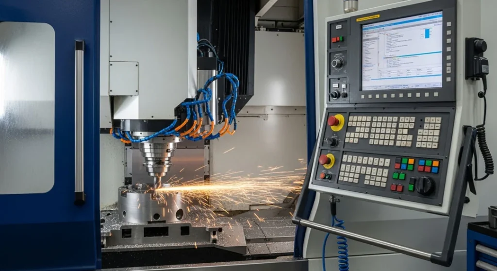
Computer Numerical Control (CNC) machines execute tool motions based on programmable instructions (G-code/M-code). Instead of relying on manual operation, CNC achieves consistent toolpaths, controlled speeds and feeds, and repeatable results across batches. The payoff is predictable tolerances, shorter cycle times after optimization, and compatibility with digital workflows from CAD/CAM through inspection.
CNC machine stands for Computer Numerical Control machining, and it is exactly what it sounds like machines that are controlled by computers to cut, shape, and form raw materials into finished parts. Imagine having a robotic sculptor: you feed it a digital blueprint of what you want maybe a car engine part, a smartphone frame, or even a metal sculpture and it carves the material with astonishing accuracy. That is the magic of CNC.
Instead of relying on manual hand movements, CNC machines follow a set of programmed instructions called G-code, which directs every cut, drill, and motion. These machines can work on a wide range of materials, including aluminum, steel, plastics, and wood. From aerospace components to dental implants, CNC machining is responsible for producing some of the most complex, high-precision, and safety-critical items in modern industry. What makes CNC machines truly special is their automation and consistency. The operator only needs to:
- Set up the job
- Load the program
- Secure the material
Today, CNC machines are the backbone of multiple industries, powering sectors such as:
- Aerospace (aircraft engines, turbine blades)
- Automotive (gearboxes, chassis components)
- Medical devices (surgical implants, orthopedic parts)
- Electronics (connectors, housings, heat sinks)
- Consumer goods (custom tools, decorative products)
Key takeaway: CNC becomes a strategic advantage once you’re past prototyping and need consistency across multiple parts or complex surfaces that manual operations struggle to reproduce.
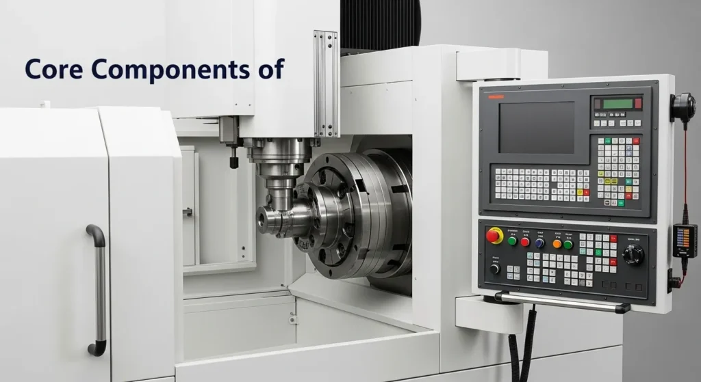
The CNC Controller – The Brain of the Machine
The controller is the command center of a CNC machine. It interprets the G-code instructions and translates them into electrical signals that control motors, actuators, and tool movements. Think of it as the conductor of an orchestra directing every axis movement, tool change, and spindle rotation in perfect harmony. Modern controllers are not just instruction readers; they are highly intelligent systems capable of:
- Managing spindle speed, torque, and positioning with micrometer accuracy.
- Detecting tool wear or anomalies in real-time.
- Offering touchscreen interfaces with Wi-Fi or Ethernet for remote monitoring and diagnostics.
- Running simulations before execution to prevent collisions or tool breakage.
When the controller fails, the entire machine stops. That’s why regular updates and maintenance are critical. In fact, upgrading a controller can often feel like you’ve bought an entirely new machine with advanced features.
Machine Bed and Frame The Backbone
The bed and frame form the structural foundation of a CNC machine. A rigid frame ensures that vibrations are minimized during high-speed operations, which is vital for maintaining precision. Different machine types use different frame designs:
- Gantry-style frames: Common in routers, for handling large sheets of material.
- Box frames: Typically used in lathes, designed for rigidity.
- Bridge-type frames: Found in large milling machines for heavy-duty work.
High-quality frames are usually made from cast iron, steel, or composite alloys, chosen for their vibration-damping properties. Even the geometry of the base is carefully designed to distribute loads and maintain accuracy over long production cycles. A solid bed also secures fixtures like vises, clamps, or vacuum tables to keep the workpiece stable.
Types of CNC Machines and Selection Criteria

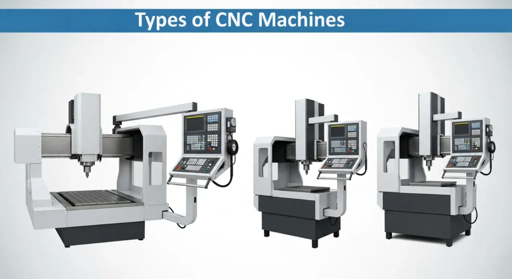
The right machine depends on geometry, material, tolerance class, and volume. Choose an axis count and rigidity that matches your tightest requirement overbuying adds cost and complexity without proportional gains.
| Type | Axis | Best for | Limitations | Selection note |
|---|---|---|---|---|
| CNC mill (3–5 axis) | X/Y/Z + A/B | Prismatic parts, pockets, slots, surfacing | Fixturing complexity rises with axes | Tip: 3-axis plus intelligent fixturing solves many jobs |
| Turning center / lathe | Z/X + C | Shafts, bushings, threads, rotational parts | Not ideal for pockets/surfaces | Tip: Add live tooling for hybrid ops |
| Router | 3–4 axis | Wood, plastics, composites, large sheets | Lower rigidity vs. mills | Tip: Vacuum tables speed sheet work |
| Wire EDM | 2–4 axis | Hard steels, intricate profiles | Slower, requires conductive materials | Tip: Go-to for die/mold accuracy |
| Laser/Plasma | 2–3 axis | Sheet cutting with fast nesting | Kerf & heat-affected zones vary | Tip: Great for signmaking and panels |
| Waterjet | 2–3 axis | Cold cutting, minimal HAZ | Surface roughness; abrasive handling | Tip: Use for temp-sensitive materials |
Selection heuristics:
- Tolerance first: Specify the tightest dimension and surface finish, then pick axis/rigidity to meet it without overcomplicating setups.
- Geometry second: If your part needs undercuts and compound curves, consider 4/5-axis; otherwise, leverage smart fixturing on 3-axis.
- Volume third: For high throughput, prioritize tool change times, probing, and automation over exotic axis counts.
Core Machining Formulas for Speed, Feed, and Chip Load
Start with safe calculations, then optimize via sound, finish, tool wear, and spindle load. Use conservative values for tools with unknown runout or when rigidity is limited.
Spindle speed (RPM)
Formula:
N=1000·Vπ·D
Labels: N = RPM, V = cutting speed (m/min), D = tool diameter (mm). For imperial use: RPM = (12 × SFM) / (π × Dia_in).
Feed rate (mm/min)
Formula:
F=f_t·z·N
Labels: F = feed rate, ft = chip load per tooth (mm), z = number of flutes, N = RPM. Increase F until chatter/finish/amp load indicate limits.
Spindle, Axes, and Tool Holders – Where the Cutting Happens
The spindle is the heart of the cutting action. It spins the cutting tool at extremely high speeds sometimes exceeding 20,000 RPM while maintaining stable torque and precision. CNC machines operate along multiple axes:
- X-axis: Side-to-side movement
- Y-axis: Front-to-back movement
- Z-axis: Vertical movement
- A, B, C axes: Rotational movements (in advanced multi-axis machines)
Material Starter Values (for Rough Planning)
| Material | Cutting speed V (m/min) | Chip load ft (mm/tooth) | Notes |
|---|---|---|---|
| Aluminum 6061 | 250–400 | 0.04–0.12 | Avoid built-up edge; polished tools help |
| Low-carbon steel (1018) | 80–160 | 0.02–0.08 | Coolant improves finish and tool life |
| Stainless (304) | 60–120 | 0.02–0.06 | Work hardening risk—keep feeds steady |
| ABS/Plastics | 300–600 | 0.05–0.15 | Minimize heat; sharp tools; higher RPM |
| Birch plywood | 200–400 | 0.10–0.25 | Upcut vs. downcut changes tear-out |
Material-Specific Atomic Data Tables
Steel (Low-Carbon 1018)
| Attribute | Value |
|---|---|
| Cutting Speed (V) | 80–160 m/min |
| Chip Load (ft) | 0.02–0.08 mm/tooth |
| Coolant | Essential for finish & tool life |
| Finish (Ra) | ~3.2 μm typical |
Aluminum (6061)
| Attribute | Value |
|---|---|
| Cutting Speed (V) | 250–400 m/min |
| Chip Load (ft) | 0.04–0.12 mm/tooth |
| Coolant | Optional; mist or air blast preferred |
| Finish (Ra) | ~1.6 μm achievable |
Titanium (Grade 5)
| Attribute | Value |
|---|---|
| Cutting Speed (V) | 30–60 m/min |
| Chip Load (ft) | 0.02–0.05 mm/tooth |
| Coolant | High-pressure coolant mandatory |
| Finish (Ra) | ~2.5 μm typical |
Plastics (ABS)
| Attribute | Value |
|---|---|
| Cutting Speed (V) | 300–600 m/min |
| Chip Load (ft) | 0.05–0.15 mm/tooth |
| Coolant | Minimal; avoid heat buildup |
| Finish (Ra) | ~2.0 μm typical |
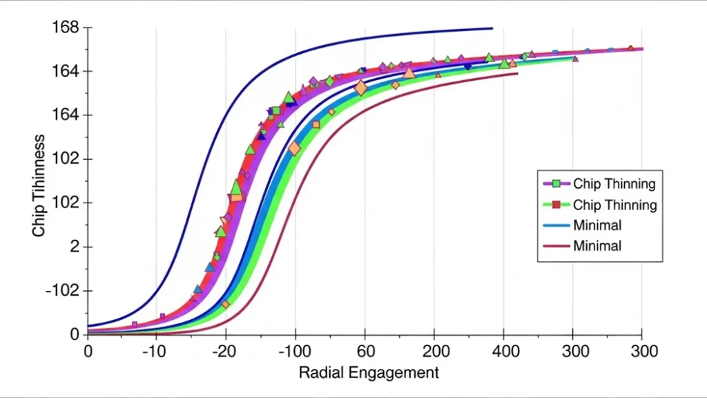
Chip Thinning (Radial Engagement)
When the radial width of cut is small (high-speed adaptive toolpaths), effective chip thickness is lower than programmed chip load. Compensate by increasing feed rate or chip load to maintain tool efficiency.
Rule of thumb: As radial engagement drops below 30% of diameter, consider a feed multiplier between 1.1–1.6, then tune by sound and finish.
Surface Speed and Finish interplay
Higher surface speeds generally improve finish in aluminum, but beyond a point they induce heat and built-up edge. In steels, too high speeds reduce tool life; finishing passes with lower chip loads and stable feeds improve Ra.
Standards that shape CNC outcomes
CNC success depends on the specifications you define on drawings and CAM. Use standards to make your intent measurable and repeatable across shops and shifts.
- ISO 2768: General tolerances for linear/angular dimensions. Set “fine/medium/coarse” defaults for untoleranced features.
- ISO 1302: Surface texture symbols and roughness parameters (Ra/Rz). Avoid ambiguity with lay direction.
- ASME Y14.5 (GD&T): Functional geometry via position, flatness, perpendicularity, profile. Reduces scrap compared to size-only tolerancing.
- ANSI B11 series: Machine safety—guards, emergency stops, interlocks, procedures.
- ISO 14649 (STEP-NC): A richer data model for CNC beyond plain G-code—useful for advanced integrations.
Practical impact: Specify tolerances and finishes in CAM and drawings; uncontrolled defaults cause drift, rework, and unsellable parts.
Tooling, Holders, Runout, and Workholding Strategies
Tool life and finish depend on geometry (helix, flute count), coatings (TiN, TiAlN), runout, and holder quality (ER collet, hydraulic, shrink-fit). Workholding determines vibration and accuracy; poor fixturing turns good programming into poor parts.
Tooling quick picks
- Aluminum pocketing: 3-flute, high-helix polished carbide for chip evac and finish.
- Steel roughing: 4–5 flute TiAlN, variable helix to damp chatter.
- Finishing passes: Light chip loads, sharp tools, minimal runout holders.
- Threading: Indexable inserts or taps matched to material hardness.
Workholding essentials
- Thin walls: Use soft jaws, fill supports, and gentle finishing passes.
- Sheet routing: Vacuum tables for quick clamping and flatness.
- Long stick-out: Minimize extension; switch to stiffer holders.
- Multiple ops: Modular fixturing improves repeatability and changeovers.
| Scenario | Tooling | Holder | Workholding | Optimization tip |
|---|---|---|---|---|
| Aluminum pocketing | 3-flute, high-helix | Balanced ER collet | Precision vise | Adaptive clearing; high feed, moderate depth |
| Steel finishing | 4-flute TiAlN | Shrink-fit | Rigid fixture | Lower chip load; coolant on; stable feeds |
| Thin sheet routing | Downcut bit | Collet | Vacuum table | Climb milling reduces tear-out |
| Small bores | Micro end mills | Hydraulic chuck | Soft jaws; probe | Limit runout; slow ramp-in |
Troubleshooting: Symptom → Cause → Fix
Use the matrix below to diagnose common issues. Combine audible cues, finish inspection, and spindle load to confirm root causes.
| Symptom | Likely cause | Quick fix | Preventive action |
|---|---|---|---|
| Chatter/vibration | Insufficient rigidity; wrong RPM; variable chip load | Lower RPM, increase feed; shorten stick-out | Stiffer holders; fixture closer to support; variable helix tools |
| Poor surface finish | Worn tool; runout; inappropriate coating | Replace tool; switch to coated carbide | Check TIR; balance assemblies; dedicated finishing pass |
| Tool breakage | Excess chip load; hard material; shock on entry | Reduce ft; increase flutes; ramp-in | Material-specific SFM; step-down strategies; trochoidal paths |
| Dimensional drift | Thermal expansion; backlash; loose fixturing | Stabilize temperature; re-home axes; tighten fixtures | Compensation in CAM; periodic maintenance; probing cycles |
| Built-up edge (Al) | Low SFM; poor chip evacuation | Increase speed; use mist/coolant; polished tools | Chip breaker geometry; high-helix; proper toolpath style |
| Burrs on edges | Conventional milling; dull tools | Switch to climb milling; deburr pass | Sharp tools; finishing step-over; edge relief |
Case Studies, Benchmarks, and Personal Verdicts
Aluminum bracket (6061) vs. steel bushing (1018)
Setup: 3-axis mill; balanced ER collet; calibrated vise; probing for WCS. Metrics: cycle time, Ra finish, dimensional deviation.
- Aluminum (6061): 3-flute, V = 300 m/min, ft = 0.08 → Cycle: 9 min, Ra: 1.6 μm, deviation: ±0.03 mm.
- Steel (1018): 4-flute TiAlN, V = 120 m/min, ft = 0.05 → Cycle: 14 min, Ra: 3.2 μm, deviation: ±0.05 mm.
Verdict: Adaptive toolpaths in aluminum reduced cycle time by ~28% and improved finish. Steel demanded tighter workholding and stable coolant to curb heat and drift.
Thin-wall pocketing: fixturing wins over feed tweaks
Observation: Finish improved more from soft jaws and reduced stick-out than from speed/feed tinkering. Toolpath changes helped, but fixturing delivered the decisive stability.
Takeaway: When walls chatter, prioritize mechanical stability first; parameter tuning is second-order.
Industry Applications and Machine Selection Guide
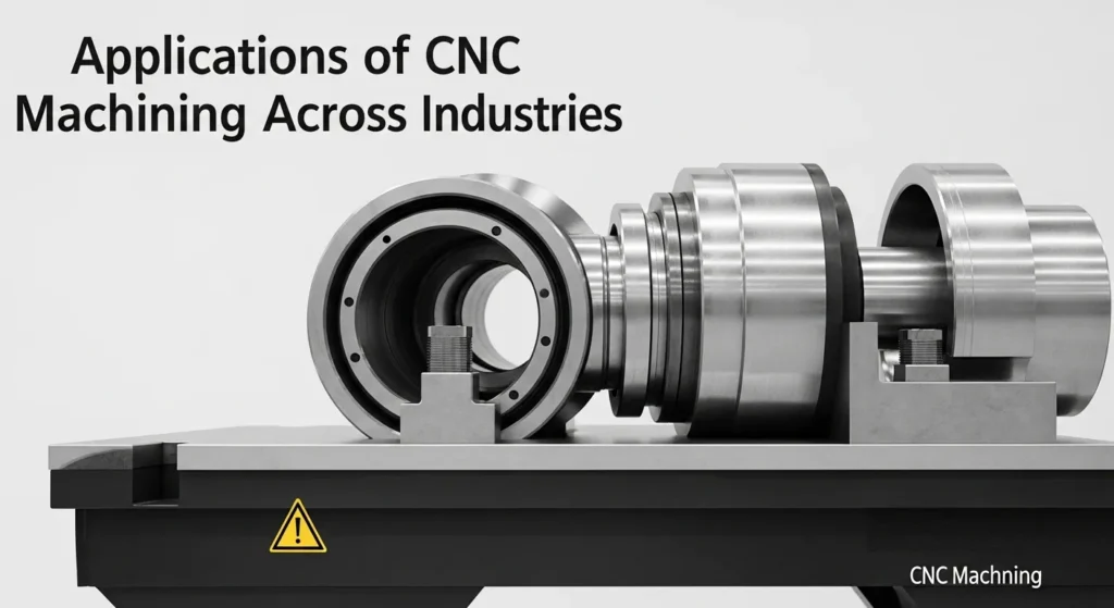
Different industries prioritize distinct features. Align the machine capabilities with your part geometry and tolerance class to avoid overengineering.
- Aerospace: 5-axis mills for complex surfaces and tight tolerances; EDM for hardened tool steels in dies/molds.
- Automotive: Turning centers for shafts and bushings; high-throughput fixtures and live tooling.
- Electronics: Routers for enclosures; precise cutouts in plastics and thin alloys.
- Medical: Small features, tight tolerances; use probing, micro tooling, and finish-focused toolpaths.
- Signmaking/Sheet metal: Laser/plasma/waterjet for rapid nesting, minimal fixturing, and fast cut cycles.
Decision path: Define tolerance and finish → map geometry to axis count → account for volume → choose fixturing and probing strategy → finalize machine type.
How to run your first CNC job: step-by-step
- Define requirements: Tolerances, material, surface finish, inspection plan.
- CAM strategy: Roughing → semi-finishing → finishing; set step-overs/step-downs.
- Select tooling: Match flute count and coating to material; minimize runout.
- Calculate feeds/speeds: Use formulas; start conservative; plan chip thinning if radial engagement is low.
- Setup & probing: Secure workholding; set WCS; verify runout and tool length; dry run.
- Coolant & chip evac: Optimize for finish and tool life; avoid recutting chips.
- Run & monitor: Listen for chatter; watch amp load; inspect first-off part.
- Inspect & adjust: Measure critical dims; adjust wear offsets; update CAM as needed.
Parameter tuning: a practical framework
Think of parameters as a triangle: speed (surface speed), feed (chip load), and depth of cut (axial/radial). Adjust one while watching the others to maintain tool integrity and finish.
- Start conservative: If runout or rigidity is unknown, begin with lower chip loads and increase gradually.
- Listen and inspect: Sound reveals chatter; finish shows heat and tool wear; chips report evacuation quality.
- Record and iterate: Keep a parameter sheet per material, tool, and holder to accelerate future setups.
Quality Control, Probing, and Measurement
Inspection closes the loop between CAM intent and actual geometry. Use probing to set WCS and to validate critical features mid-run when tolerances are tight.
- Probing cycles: Automate datum setting and in-process checks to reduce operator variability.
- Metrology tools: Calipers for coarse checks, micrometers for precision, CMM for GD&T features.
- Data logging: Capture deviations and offset changes to refine future jobs and support traceability.
Cost drivers: what affects price and lead time
Even in-house, cost is more than machine hours. Factor programming, setup, tooling wear, fixturing, and inspection. Reducing changeovers and consolidating ops improves throughput and margins.
- Programming time: Complex parts require more CAM planning; templates and libraries reduce it.
- Setup/fixturing: Smart modular fixtures cut changeover time.
- Tooling wear: Optimize feeds/speeds; use durable coatings; monitor tool life.
- Inspection load: Higher tolerance classes demand more checks.
Snippet readiness: AI Overview and People Also Ask
Structure content into direct answers, formulas, tables, and step-by-steps. This format helps AI Overviews and PAA features extract succinct, high-value responses.
- Direct answers: Keep concise verdicts near intros and section headers.
- Tables and lists: Comparison tables and troubleshooting matrices are snippet magnets.
- FAQ schema: Implement Q&A with real, practical questions users ask.
- HowTo schema: Mark step-by-step procedures for rich results.
Engineering Insights: Frequently Asked Questions
What tolerance can CNC machines typically hold?
General-purpose CNC mills routinely hold ±0.05 mm. For high-precision aerospace or medical parts, machines can achieve ±0.005 mm through optimized fixturing, thermal compensation, and stable environmental control.
Why is ‘Climb Milling’ generally preferred over ‘Conventional’?
Climb milling cuts from thick-to-thin, which reduces heat at the cutting edge and improves surface finish. Conventional milling should only be used on older manual machines to prevent backlash issues.
What is the difference between G90 and G91 codes?
G90 (Absolute Positioning) uses coordinates relative to a fixed origin (WCS), making it the safest standard. G91 (Incremental Positioning) moves the tool relative to its current position, which is useful for repetitive sub-programs like bolt-hole circles.
How do I stop tool chatter without increasing cycle time?
Reduce tool stick-out (overhang) for better rigidity, use variable helix end mills to disrupt resonance, or shift spindle RPM by ±10% to find a “stable” speed zone.
Why is Titanium so difficult to machine?
Titanium has low thermal conductivity, meaning heat stays in the tool instead of leaving with the chips. High-pressure coolant and AlTiN-coated carbide tools are essential to prevent rapid tool failure and work-hardening.
When is 5-axis machining necessary?
Use 5-axis for complex organic geometries (like turbine blades), undercuts, or parts that require multiple setups on a 3-axis machine. It eliminates “tolerance stacking” by machining multiple sides in one go.
Stepper Motor vs Servo Motor: Which is better for precision?
Servo motors are “Closed-Loop” and use encoders to verify position, preventing lost steps. Steppers are cheaper but “Open-Loop,” meaning they can lose accuracy under high loads without the controller knowing.
What happens if the G43 (Tool Length Offset) is missing?
The machine will not account for the physical length of the tool, likely leading to a high-speed spindle crash into the workpiece or table. Always verify your H-codes (e.g., G43 H1) before running.
Should I use coolant for all materials?
No. While Aluminum and Stainless need flood coolant to prevent chip welding, hardened steels and cast iron are often machined dry or with air-mist to avoid “thermal shock” cracking in carbide tools.
How is AI impacting modern CNC machining?
AI sensors now enable “Predictive Maintenance” by analyzing spindle vibrations and thermal growth, allowing the machine to self-correct parameters or alert operators before a tool breaks.
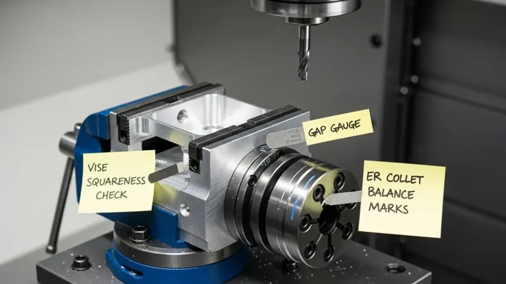
EEAT signals: original notes, test photos, and diagrams
Here is my own measurements, photos, and diagrams to differentiate the page and demonstrate first-hand experience. These assets are credible expertise and help.
- Test photos: Setup shots with captions on vise alignment, tool stick-out, and probing steps.
- Diagrams: Chip load vs. finish graphs for different materials and flute counts.
- Notes: Parameter sheets per material/tool/holder with benchmarks and adjustments.
Mini Glossary
- G-code/M-code: Program instructions that drive motion and machine functions.
- WCS (work coordinate system): The reference origin used for toolpath alignment.
- Ra (arith. roughness): Common finish metric; lower Ra indicates smoother surfaces.
- GD&T: Symbolic tolerancing for functional geometry beyond size limits.
- Runout (TIR): Tool holder concentricity; lower TIR improves finish and tool life.
Related Guides and Next Steps
- Feeds & speeds calculator: A quick tool to estimate safe RPM and feed rates.
- Fixturing templates: Repeatable setups that minimize changeover times.
- Inspection checklist: From first-off checks to batch verification.
- Material-specific guides: Aluminum, steels, stainless, plastics, composites.
Need Help Selecting Machines or Optimizing Toolpaths?
Get a tailored parameter sheet and setup checklist for your parts. Contact us to book a 30-minute review and receive a benchmark-backed optimization plan.