Few things are more frustrating than building a circuit that should work only to hear a hiss in your audio, see flickering LEDs, or get unstable sensor readings. The culprit is usually signal noise, the invisible interference that sneaks into your design. The good news? Most noise problems can be solved with proven techniques like shielding, grounding, filtering, and smart component choices.
This guide explains why noise happens in electronic circuits and gives you five practical, research-backed solutions to eliminate it so your projects run clean, stable, and professional.
What Is Signal Noise in Electronics?
Signal noise is any unwanted electrical disturbance that interferes with the desired signal. It can appear as:
Static in audio circuits
Random spikes in sensor readings
Voltage fluctuations in digital systems
Crosstalk between high-speed traces
Noise is inevitable, but it can be minimized. According to Springer’s Lecture Notes in Analog Electronics, every component resistors, diodes, transistors—introduces some level of noise. The challenge is keeping it below the threshold where it affects performance.
Quantitative Foundation: Measuring the Noise Floor
Engineers quantify the severity of noise using two fundamental metrics: the Signal-to-Noise Ratio and the calculation of the unavoidable minimum noise level (the noise floor).
1. Signal-to-Noise Ratio (SNR) in Decibels (dB)
SNR is the ratio of signal power (Psignal) to noise power (Pnoise). It is always expressed logarithmically in decibels (dB) because of the massive range of power values encountered in electronics. SNR = 10 log 10 ( P signal P noise ) dB , V n = 4 k B T R Δf Goal: A high SNR (e.g., 90 dB for professional audio) is necessary for high-fidelity systems, meaning the desired signal is 1 billion times stronger than the noise power.
2. Thermal Noise Voltage (Johnson–Nyquist Noise)
Thermal noise is the minimum, irreducible noise floor present in all conductors due to the random motion of electrons. It sets the ultimate limit on a circuit’s sensitivity.
Where:
- Vn = RMS Noise Voltage (V)
- kB = Boltzmann Constant (1.38 × 10⁻²³ J/K)
- T = Temperature in Kelvin (K)
- R = Resistance (Ω)
- Δf = Bandwidth (Hz)
Engineering Insight: The formula shows that reducing noise requires reducing the Bandwidth (Δf) or the Resistance (R).
Theoretical Limits: Shannon-Hartley and Noise Figure
Noise is the single factor that limits the data rate of any communication link. These formulas define the absolute best-case performance for electronic systems.
1. Shannon-Hartley Theorem (Channel Capacity)
This theorem defines the maximum theoretical data rate (C) a communication channel can reliably achieve, given its bandwidth (B) and its Signal-to-Noise Ratio (S/N ratio).
C = B log 2 ( 1 + S N ) ,
F = SNR input SNR output ,
NF = 10 log 10 ( F ) Where:
- C = Channel Capacity in bits per second (bps)
- B = Bandwidth in Hertz (Hz)
- S/N = Signal-to-Noise power ratio (linear, not dB)
Industry Standard: This is the guiding principle for designing Wi-Fi, cellular, and satellite communication systems. It proves that to increase capacity, you must increase either the bandwidth or the SNR.
2. Noise Figure (NF) and Noise Factor (F)
The Noise Figure is the industry-standard specification for how much noise a component (like an amplifier or mixer) adds to a signal as it passes through. Lower NF values are critical for satellite receivers and medical instruments. Troubleshooting Insight: If an amplifier has an NF of 3 dB, it means the SNR at the output will be 3 dB worse than the SNR at the input.
Case Studies: Noise Impact on Systems
- Audio Systems: Noise floor in high-gain amplifiers limits the dynamic range. A poor noise floor (SNR < 70 dB) introduces audible hiss.
- Communication Systems: Noise is the ultimate factor limiting data rates over a channel (Shannon-Hartley theorem). Higher noise forces lower data throughput.
- Precision Sensors: Thermal noise in the sensor’s resistor element directly affects the smallest voltage change that can be reliably measured.
Comparison and Physics of Noise Types
Different noise sources require different mitigation strategies:
| Noise Type | Source | Effect | Mitigation |
| Thermal Noise | Resistors, conductors | Random voltage fluctuations | Reduce bandwidth, cooling |
| Shot Noise | Diodes, transistors | Current fluctuations across junctions | Larger $\text{DC}$ bias currents, averaging |
| $\text{EMI}$ | External fields (motors, clock lines) | Spikes, high-frequency distortion | Shielding, twisted pairs |
| Ground Loop | Poor wiring, multiple ground points | Low-frequency hum ($\sim 60 \text{ Hz}$) | Star grounding, isolation |
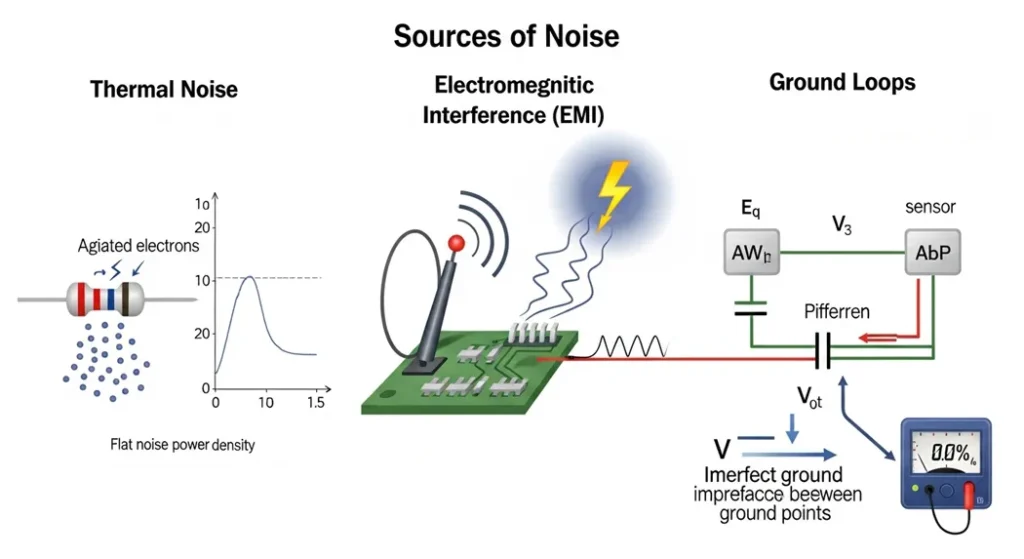
Diagram: Common Sources of Signal Noise
Types & Sources of Noise (Research Data)
| Noise Type | Cause | Impact on Circuits | Research Insight |
|---|---|---|---|
| Thermal Noise | Random motion of electrons in resistors | Adds background hiss | Springer |
| EMI (Electromagnetic Interference) | External RF sources, switching supplies | Crosstalk, resets | IEEE EMI Guidelines |
| Ground Loops | Multiple ground paths | Hum in audio, unstable signals | DigiKey Ground Loops |
| Crosstalk | Parallel traces on PCB | Data corruption | HillPublisher Research |
| Sensor Noise | Environmental interference | Fluctuating readings | MakerPro Tutorial |
Five Proven Ways to Eliminate Noise
1. Use Bypass Capacitors & Ferrite Beads
Place 0.1µF ceramic capacitors close to IC power pins.
Add ferrite beads in series with supply lines to block high-frequency noise.
Texas Instruments notes that combining ferrite beads with bypass capacitors forms an effective Pi filter for noise suppression (TI Application Note).
In practice, many hobbyists notice that simply adding a capacitor near a microcontroller instantly stabilizes erratic resets. It’s one of the cheapest and most effective fixes.
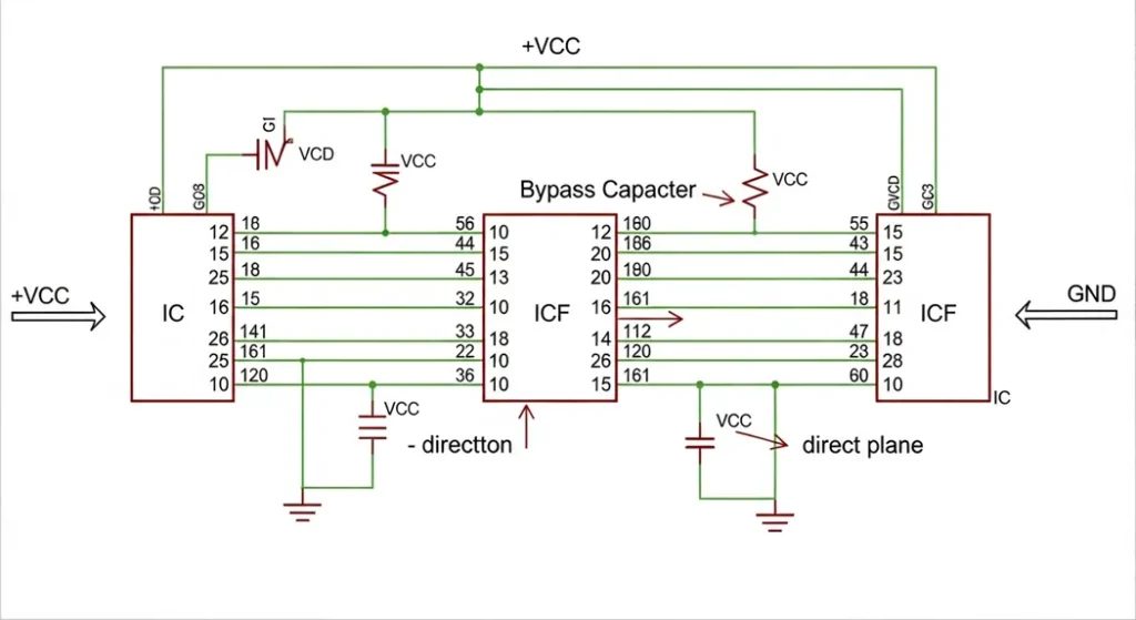
Visual: Capacitor Placement in Circuit Design
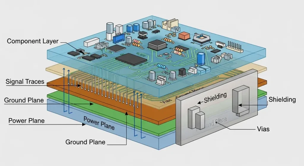
2. Shielding & PCB Layout Best Practices
Use ground planes to minimize loop area.
Separate analog and digital sections.
Shield sensitive circuits with metal enclosures or board-level shields.
AndwinPCB highlights that via stitching and controlled impedance traces reduce EMI dramatically.
For example, in audio amplifier builds, simply routing signal traces away from power lines often eliminates background hum without adding extra components.
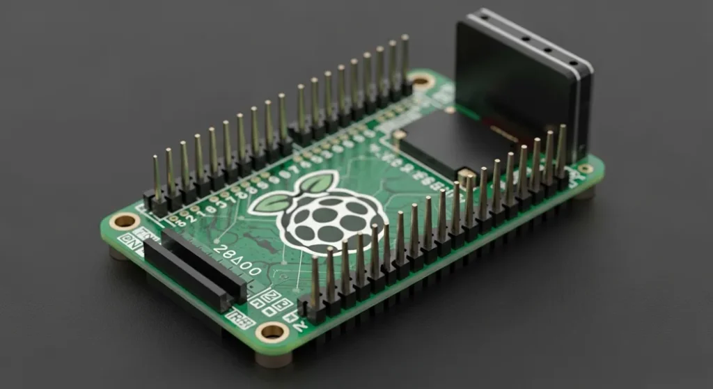
Visual: Example of a Well-Shielded PCB Layout
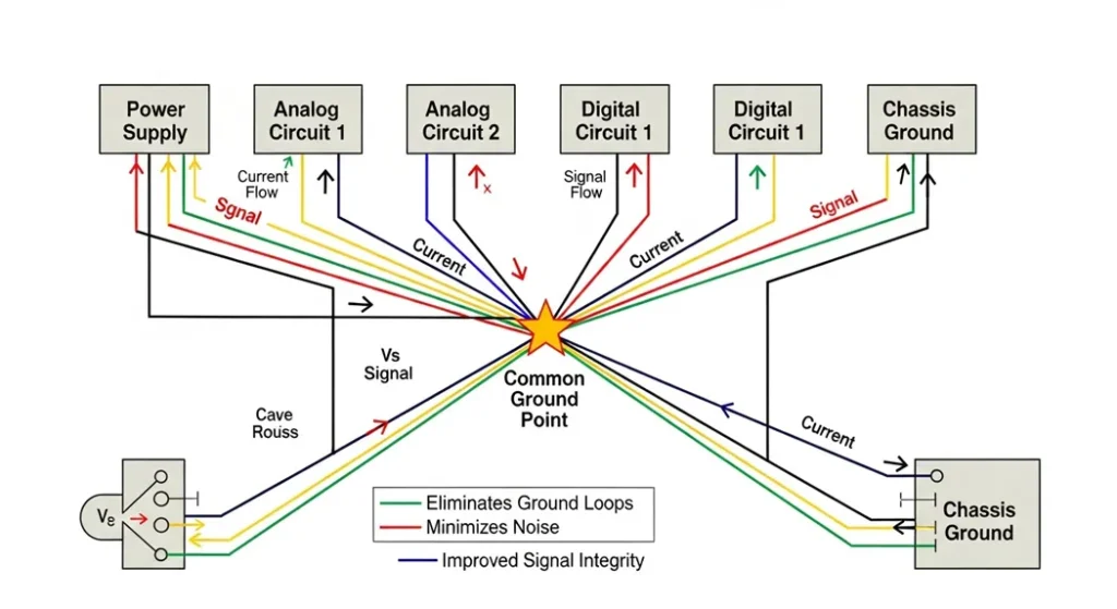
3. Grounding & Avoiding Ground Loops
Always use a single-point ground (star grounding).
Avoid daisy-chaining grounds.
Ground loops are a major cause of hum in audio circuits. DigiKey explains that loops allow unwanted current paths that inject noise into sensitive signals.
A common scenario is connecting a laptop to an audio mixer while both are plugged into different outlets. The resulting hum disappears once the ground loop is broken with proper grounding or isolation.
Visual: Star Grounding Diagram
Quantitative Troubleshooting: Designing RC Filters
While software filters are useful, hardware filtering remains the most robust solution for eliminating high-frequency sensor noise and low-frequency mains hum. The RC low-pass filter is the simplest and most common tool.
1. Calculating the Filter Cutoff Frequency (fc)
The cutoff frequency (fc) is the point at which the filter begins to significantly attenuate the signal (reducing the power by half, or −3 dB). All frequencies above fc are attenuated. f c = 1 2 π R C Where:
fc = Cutoff Frequency in Hertz (Hz)
- R = Resistance in Ohms (Ω)
- C = Capacitance in Farads (F)
Case Study: To filter out a 60 Hz mains hum, you would design an RC filter with a cutoff frequency significantly below 60 Hz, ensuring the hum is heavily attenuated while your signal remains intact.
2. Filter Roll-Off Performance
A simple (single-pole) RC filter reduces the noise by 20 dB for every factor of ten increase in frequency above the cutoff point (a 20 dB/decade slope). To increase the steepness of the attenuation, one must cascade multiple filter stages (two-pole, three-pole, etc.).
4. Filtering Sensor & Audio Signals
Apply moving average filters in microcontroller code (MakerPro).
Use low-pass RC filters for analog signals.
In audio, add shielded cables and twisted pairs to reduce interference.
In one Arduino project, a temperature sensor produced wild ±5°C swings. Adding a capacitor across the sensor and applying a moving average filter in code reduced the error to ±0.2°C—making the readings reliable enough for real-world use.
5. Component Selection & Signal Conditioning
Choose low-noise op-amps and precision resistors.
Match sensor impedance with the analog front end (Analog Devices).
Use SPICE simulations to predict noise before building.
Designers often find that upgrading to a low-noise op-amp costs only a few cents more but dramatically improves performance in audio and sensor circuits.
FAQs
Q1: Why does my audio amplifier hum even when no input is connected?
A: Likely a ground loop or poor shielding. Use star grounding and shielded cables.
Q2: Can software filters completely remove noise?
A: They help, but hardware fixes (shielding, grounding, capacitors) are essential for best results.
Q3: Do ferrite beads work for all noise?
A: No. They are most effective for high-frequency EMI, not low-frequency hum.
Q4: What’s the cheapest way to reduce noise in DIY circuits?
A: Add bypass capacitors near ICs and keep wires short.
Q5: Is noise always bad?
A: In most circuits, yes. But in cryptography, random noise is sometimes used for secure key generation
Conclusion
Noise is inevitable, but it doesn’t have to ruin your projects. By combining smart PCB design, proper grounding, shielding, filtering, and component selection, you can achieve clean, stable signals. Whether you’re building a DIY Arduino project or designing high-speed digital circuits, these techniques will save you hours of frustration and make your designs more professional.
Sources
- MDPI – ANNs Predicting Noisy Signals in Electronic Circuits
- HillPublisher – High-Speed Digital Circuit Noise Research
- Springer – Lecture Notes in Analog Electronics: Noise in Circuits
- MakerPro – Clean Up Noisy Sensor Data
- Schmartboard – How to Reduce Noise in Circuits
- Analog Devices – Low Noise Signal Conditioning
- MegunoLink – Filtering Noisy Arduino Measurements
- DigiKey – Ground Loops Explained
- AndwinPCB – PCB EMI Shielding Techniques
- IEEE – Guidelines for Reducing EMI