Key Takeaways: Two-Way Switch Wiring Explained
Ever walked up a staircase and wished you could switch the light off at the top without going back down? That’s exactly what a two‑way switch is for. It lets you control the same light from two different spots like the top and bottom of the stairs, or the door and the bed in a bedroom. The trick lies in a pair of switches connected by “traveler” wires. These wires create two possible paths for electricity. The light only comes on when both switches line up on the same path, and it stays off when they don’t. Simple, but clever.
This setup isn’t just for staircases it’s handy in hallways, garages, and even offices where you want convenience and safety. And yes, you can install it yourself if you’re comfortable with basic wiring. Just don’t forget the golden rules: cut the power first, use the right tools, and follow a proper wiring diagram. For modern homes, electricians usually recommend the three‑wire method. It’s more reliable and works better with today’s lighting, especially LEDs. Also, make sure the switches you buy are rated for the load you’ll put on them cheap or mismatched switches can cause flickering or wear out faster.
Table of Contents
- What Is a Two-Way Switch?
- How Does It Work?
- Why Use Two-Way Switching?
- Wiring Methods
- Safety & Installation Tips
- Choosing the Right Switch
- Advanced Topics & Calculations
- Troubleshooting Guide
- FAQs
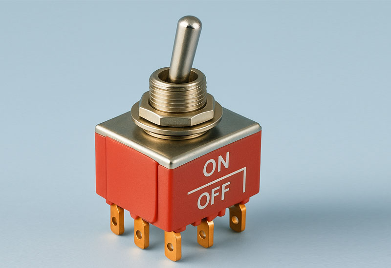
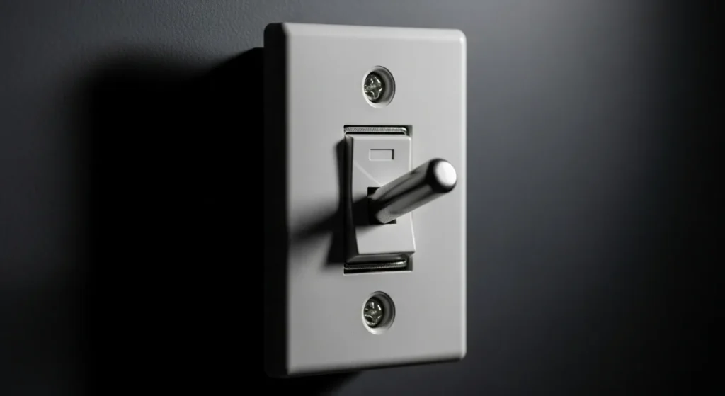
What Exactly Is a 2-Way Switch?
You’ve probably seen them before those unassuming switches on the wall that look like any other. But here’s the twist: they are part of a clever system that lets you turn a single light on or off from two different locations. Think of it like having two volume buttons on your phone—one on each side. No matter which hand you use, you can adjust the sound without fumbling around.
Wiring of a two-way switch works similarly. It has three terminals instead of two, allowing the current to flow in different directions. This setup is what you typically see in a 2-way switch diagram wiring or two-way electrical switch wiring diagram, where each terminal plays a specific role depending on how the switches are positioned. This setup is sometimes called a “staircase switch” because it’s often used on staircases where you want to control the light from both the top and the bottom. But don’t let that name limit you—these switches are incredibly versatile.
How Does It Work?


The two-way switch system is an elegant application of selective path control, enabling you to operate a single light fixture from two separate locations. This entire operation is based on the logic of either completing or breaking the circuit using two parallel routes. Each switch features three critical terminals: the COM (Common) terminal, which acts as the fixed input or output point, and the two traveler terminals (L1 and L2). The first switch receives the permanent Line (Hot) power on its COM terminal, and the second switch sends the output Switch Leg from its COM terminal directly to the light fixture. The traveler wires (L1 and L2) link the two switches, providing two parallel routes for the electricity to flow between them.
When you flip a switch, you simply move the internal contact from one traveler wire to the other. The light is ON only when both switches are connected to the same traveler. Conversely, if they are connected to different travelers, the circuit is broken, and the light is OFF. The operational principle of this circuit perfectly mimics an Exclusive OR (XOR) logic gate, where the output (the light) is activated only when the two inputs (the switch positions) are in the same state.
Why Would You Need This Setup?


If you’ve ever walked into a long hallway, turned on the light, and then stood there wondering how to turn it off again without walking all the way back, then you already know the answer. Two switches, one light or what many call 2 switches 1 light—is the practical solution. Two-way wiring solves that problem beautifully. Here are some common situations where this kind of wiring comes in handy:
Staircases
Climb the stairs safely—turn the light on at the bottom, and off when you reach the top.
Hallways
Turn the light on as you enter, and off as you exit—no awkward walks back.
Bedrooms
Control the overhead light from the door and the bed. Perfect for lazy mornings or late-night bathroom trips.
Garages
Turn on the garage light from inside the house before heading out—and turn it off once you’re safely inside the car.
Offices & Commercial Spaces
Use multiple switches to control lighting in open-plan areas or shared spaces. The idea is simple: make life easier by giving yourself control from wherever you happen to be.
Wiring It Out: What You Need to Know
Now, let’s talk about the actual wiring. There are two main ways to wire a two-way switch:
The Three-Wire Method (Modern & Most Common)
This method uses three wires:
- One connected to the live power source (phase)
- Two traveler wires connecting the two switches
- One final wire leading to the light (neutral)
Each switch has three terminals: COM (common), L1, and L2. If you’re studying a 2 way switch wiring diagram, these terminals are clearly labeled. Most 2 way electrical switch wiring setups rely on this configuration for flexibility and ease of use. Depending on how you flip the switches, the current flows through different paths—completing or breaking the circuit as needed.
It’s like choosing which lane the electricity travels through left, right, or both. This method gives you full control from either switch and is the preferred option for most homes today.
The Two-Wire Method (Older Style)
Back in the day, people used only two wires for this setup. This older style of 2 way switch wiring is still found in some homes and is often shown in a connection diagram of two way switch for reference, but it lacks the smooth control of modern systems. It worked, but not as smoothly. It functions more like a toggle—on-off-on-off—depending on how many times you flip the switches. While simpler, it’s less flexible and harder to expand. That’s why modern installations usually stick with the three-wire method.
Can You Do This Yourself?
If you’re even slightly handy with tools and comfortable working with basic electrical systems, yes—you can install a two-way switch yourself. But remember: electricity isn’t forgiving.
Before you start poking around in the walls, make sure you:
- Turn off the main power supply
- Use insulated tools and wear protective gloves
- Double-check everything before restoring power
- Never work in damp or wet conditions
- Don’t overload the circuit beyond its capacity
If you’re unsure at any point, stop and call a licensed electrician. It’s better to be safe than sorry.
Safety First: Don’t Skip the Basics
Even if you’ve done a few DIY projects before, never underestimate the importance of safety when dealing with electricity. Here are some quick tips to keep in mind:
- Always turn off the power before starting any wiring.
- Use a voltage tester to ensure no live current is running through the wires.
- Keep your workspace dry and organized.
- Avoid touching exposed wires or terminals.
- Ensure proper earthing and insulation.
- Never force a wire into a tight connection it could cause overheating later.
Take your time. Rushing through electrical work can lead to dangerous mistakes.
Choosing the Right Switch
Not all switches are created equal. In India, some trusted brands offer high-quality two-way switches that work well in setups like 2 lights to one switch or 1 light two switches depending on your circuit design combining durability with safety. Here are a few options worth considering:
| Brand | Model | Current Rating |
|---|---|---|
| Legrand | White Legrand Britzy | 16 Amp |
| Maddox | White Modular Two-Way Switch | 16 Amp |
| Schneider Electric | Two-Way Modular Switch | 10 Amp |
| Affonso | Modular Switch | 10 Amp |
| Arcitech | 2-Way Electrical Switch | 6 Amp |
These switches come in sleek designs and are built to last. Choose one that matches your load requirements and aesthetic preferences.
Advanced Topics: Calculations & Real-World Applications
Voltage Drop Calculation
Long traveler runs can reduce LED brightness and risk non‑compliance. The voltage drop is given by:
V drop = I ⋅ ( R out + R return ) , R = ρ ⋅ L A
Example:
- Load: 0.8 A LED driver
- Conductor: 1.5 mm² copper
- Round‑trip length: 20 m
R = 0.0175 ⋅ 20 1.5 ≈ 0.233 Ω V drop = 0.8 ⋅ 0.233 ≈ 0.186 V
This is ~1.55% of 12 V supply. If voltage drop exceeds 3%, upsize the conductor to maintain brightness and compliance.
LED Driver Inrush Current
Modern two‑way circuits often drive LED drivers, which exhibit high inrush currents:
I inrush ≈ 8 − 12 × I rated ( 10 − 20 ms )
Fix: Use switches rated for inductive loads (AC‑15 / IEC 60947‑5‑1) or LED‑specific ratings per manufacturer.
Neutral and Switching Method Matrix
| Topology | Description | Smart Switch Note |
|---|---|---|
| Switch‑leg without neutral | Only line and switched leg present | Not suitable for smart switches |
| Neutral at fixture | Neutral terminated at light fitting | Requires rewiring for smart switches |
| Neutral in box | Line, neutral, and switched leg in box | Fully compatible with smart switches |
Contact Rating vs Load Type
| Load Type | Suggestion |
|---|---|
| Resistive (incandescent) | Standard rating OK |
| Inductive/driver (LED, CFL) | De‑rate by 30–50% or use LED‑rated switches |
Safety Threshold: Loop Impedance
Protective devices must trip under fault conditions. The acceptable loop impedance is: Z s ≤ U 0 I a Where:
- Zs = loop impedance
- U0 = nominal voltage
- Ia = fault current causing protective device operation
Excessive Zs risks non‑tripping under fault, compromising safety.
Quantitative Analysis: Load Calculation and Electrical Principles
While a two-way circuit is conceptually simple, professional installation requires adherence to circuit theory for safety and efficiency.
1. Electrical Principle of Two-Way Switching
The circuit works by placing the two switches in series with the load, but the switches operate to select one of two parallel paths (the traveler wires). The entire setup is placed in the line (hot) conductor to control the flow to the load. The circuit must satisfy Kirchhoff’s Voltage Law: the sum of voltage drops around the loop must equal the source voltage.
2. Voltage Drop and Efficiency
The resistance ( R ) of the traveler wires is crucial in long runs (e.g., hotel hallways). Current flowing through these wires causes a voltage drop ( ΔV ), reducing power delivered to the light and causing heat dissipation:
Δ V traveler = I load ⋅ R traveler
Example: If the load current (I) is 5A and the resistance ( R ) of a long traveler wire run is 0.5Ω , the voltage drop across the traveler is
5A⋅0.5Ω=2.5V . This loss reduces efficiency and limits the circuit’s maximum length.
3. Load Current Calculation
The maximum load current (Itotal ) determines the minimum required wire gauge and switch current rating (Ampacity). For safety, both must exceed the calculated value by at least a 125% safety margin: I total = P load V source
Common Problems & Fixes: Diagnostic Troubleshooting
Always disconnect power at the breaker before performing continuity checks with a multimeter (Ohms mode).
| Symptom / Fault | Primary Cause | Fix / Diagnostic Check |
|---|---|---|
| Light Doesn’t Turn On (Circuit dead) | Line/Hot wire is missing or the circuit breaker has tripped. | Verify power at the COM terminal of the first switch (with power ON). If power is present, check traveler wire continuity between both switches (with power OFF) to ensure the path is complete. |
| Light Only Works from One Switch | One of the traveler wires is loose, broken, or miswired (e.g., connected to Neutral). | Miswiring: Ensure the Line (Hot) and Switch Leg wires are connected only to the COM terminals, and the travelers are connected to the L1/L2 terminals. |
| Flickering / Intermittent Operation | Loose connection at the terminal screw or faulty switch mechanism. | Inspect loose terminals: Tighten all terminal screws to the required torque specification (usually found on the device). Replace the switch if tightening terminals doesn’t resolve the issue. |
Wiring Standards & Safety Compliance
Compliance with electrical codes is mandatory for safety, performance, and insurance/inspection purposes.
1. International and National Standards
- IEC 60669 (Switches): This standard governs the testing and functional requirements for switches used in household and similar fixed electrical installations, ensuring the switch can reliably break the circuit current.
- NEC (National Electrical Code – US): Requires that all switching must occur only in the Line (Hot) conductor. NEC 404.2 prohibits switching the Neutral wire, as it leaves the fixture energized and dangerous.
- Wire Sizing: NEC and IEC standards provide tables that mandate the minimum wire gauge based on the circuit breaker rating and ambient temperature (Ampacity).
2. Wire Color Codes and Identification
- NEC: Line/Hot is typically Black or Red. Travelers are often Black/Red, but sometimes a white wire is used and must be re-identified using black or red tape as Hot. Neutral is White.
- IEC: Line/Phase is Brown or Black. Neutral is Blue. Travelers are often Brown/Black but must be clearly separated and identified as part of the switched line circuit.
- Safety Rule: Never connect the Line (Hot) wire to a Blue or White wire without re-identification, as these colors are reserved for Neutral conductors.
Final Thoughts: It’s Not Just About the Light
Two-way switch wiring is more than just a technical detail it’s about making your home smarter, safer, and more convenient. Whether you’re installing it for the first time or upgrading an old system, understanding how it works puts you in control literally.
And if you ever feel overwhelmed, remember: every expert was once a beginner. So take your time, follow the steps, prioritize safety, and soon enough, you’ll be flipping switches like a pro from either end of the hallway.
Frequently Asked Questions (FAQ)
Can I use a two-way switch for LED lighting?
Yes, but ensure the switch’s rating is compatible with the LED driver’s inrush current. Modern switches are designed for this, but with large banks of LEDs, inrush current can be high, potentially damaging a lower-quality switch over time.
What’s the difference between two-way and three-way wiring?
There is no electrical difference; the terms are regional: “Two-way” is the common term in IEC/UK/EU standards, while “Three-way” is the common term in NEC/US/Canadian standards. Both refer to a circuit controlling a load from two separate locations.
Which wire is the traveler in IEC vs NEC standards?
The traveler wires carry the switched Line/Phase between the two switches. In NEC systems, these are typically Black or Red (and sometimes re-identified White). In IEC systems, these wires would be Brown or Black, but are primarily identified by their function of connecting the L1 and L2 terminals of the two switches.
What does the “COM” terminal mean?
The COM terminal stands for Common. It is the terminal where the circuit’s main power enters the switch (from the Line/Hot wire) or where the switched power exits the switch (to the load/light).
Can I control a light from more than two locations?
Yes. To control a light from three or more locations, you’ll need to add one or more four-way (crossover) switches between the two two-way switches. This is called multiway switching and is perfect for long hallways, large rooms, or commercial spaces.
What happens if I wire the travelers incorrectly?
If travelers are swapped or incorrectly connected, the light may work from only one switch, not work at all, or behave unpredictably. Always double-check connections against the wiring diagram.
Can I use smart switches in a two-way configuration?
Yes, but you need specific smart switches designed for multi-way setups. Some systems use a main smart switch with auxiliary remotes, while others require neutral wires at all switch locations. Check manufacturer specifications.
Why is my two-way switch buzzing or getting hot?
Buzzing or heating usually indicates:
- Overloaded switch (exceeding current rating)
- Loose connections
- Faulty switch mechanism
Incompatibility with the load type (especially LED/CFL drivers)
What wire size should I use for two-way switching?
For most residential lighting circuits:
- 1.5 mm² (14 AWG) for up to 10-16A circuits
- 2.5 mm² (12 AWG) for higher loads or longer runs
Always follow local electrical codes for specific requirements.
Can I convert a one-way switch to two-way?
Yes, but you’ll need to:
- Install a second two-way switch at the new location
- Run a 3-core cable between the switches (for travelers)
- Rewire the existing switch box
- Ensure proper connections at both ends
Are there wireless alternatives to wired two-way switching?
Yes, wireless options include:
- RF remote switches
- Smart home systems (WiFi/Zigbee/Z-Wave)
- Battery-operated remote switches
These eliminate the need for running traveler wires but require batteries and may have reliability considerations.
What safety certifications should I look for in two-way switches?
Look for these safety marks:
- ISI mark (India)
- CE mark (Europe)
- UL listing (USA/Canada)
- IEC 60669 compliance
- Rated for your country’s voltage (230V/120V)
What should I do if my two-way switch feels hot to the touch?
Immediately turn off the power at the breaker. A hot switch usually indicates overloading, poor connections, or a faulty switch. Have a qualified electrician inspect the wiring, connections, and load compatibility.
Is a neutral wire required for smart two-way switches?
Most smart switches require a neutral wire for powering their internal electronics. Check the specific switch’s requirements. If your existing wiring doesn’t have a neutral in the switch box, you may need to rewire or choose a smart switch designed to work without a neutral (though options are limited).