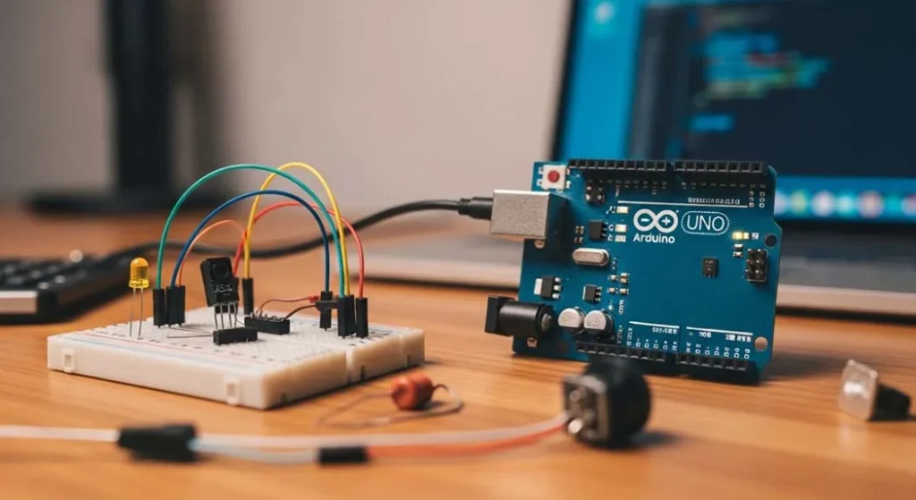
Arduino to ESP32 Every Microcontroller Skill You Need, From First Blink to WiFi IoT
Not another copy-paste-and-pray tutorial. This is the engineering guide GPIO physics, ADC precision tricks, I2C protocol internals, debouncing that actually works, and ESP32 WiFi with proper power management.
By an Embedded Systems Engineering Practitioner Oliver Adams 18 min read
⚡ Key Takeaways
- Arduino Uno’s ATmega328P runs at 16MHz with 2KB RAM every byte counts. ESP32 runs at 240MHz dual-core with 520KB RAM and built-in WiFi/BLE. Different chips, different design constraints, same fundamental GPIO principles.
- digitalWrite() takes ~5µs on Arduino but direct port manipulation (PORTB |= (1<<5)) takes ~62ns 80× faster. When bit-banging protocols or generating precise timing, skip the Arduino abstraction layer.
- The Arduino ADC is 10-bit (0-1023), ESP32 is 12-bit (0-4095), but ESP32’s ADC is notoriously noisy and non-linear above 3.1V. Apply multisampling (64 samples averaged) and use the built-in calibration API for readings within ±1% accuracy.
- Button debouncing isn’t optional a mechanical switch bounces for 1-15ms, generating dozens of false triggers. Use 10kΩ pull-up + 100nF cap for hardware debounce, or track millis() in software with a 50ms lockout window.
- I2C runs on just 2 wires (SDA + SCL) with built-in addressing for up to 127 devices. The LCD at 0x27, your sensor at 0x68, the EEPROM at 0x50 all sharing the same bus. But add 4.7kΩ pull-up resistors or nothing works.
- ESP32 WiFi draws 120-240mA during transmission a CR2032 can’t supply this. Use 18650 Li-ion cells with proper low-quiescent-current regulators. Deep sleep at 10µA + periodic wake = years of battery life on IoT sensors.
- Serial.begin(115200) is your most powerful debugging tool print variables, timing, and state transitions to Serial Monitor. 90% of firmware bugs are found by strategically placed Serial.println() calls, not by staring at code.
Path 2: Microcontrollers Arduino to ESP32
-
★Complete Microcontroller GuideYOU ARE HERE Unified guide covering all five core microcontroller topics
- 1Arduino Uno Setup & First BlinkInstall IDE, upload code, blink your first LED
- 2Digital Inputs Buttons & SwitchesRead physical inputs and control outputs
- 3Analog Sensors & PotentiometersADC, voltage reading, and sensor calibration
- 4LCD Displays via I2C ProtocolShow sensor data on a screen you can read
- 5ESP32 Your First WiFi ProjectTransition from Arduino to IoT-connected devices
Table of Contents
- What Is a Microcontroller & Why Arduino/ESP32
- Arduino Uno Setup & First Blink The Real Way
- GPIO Deep Dive What Actually Happens at the Pin
- Digital Inputs Buttons, Switches & Debouncing
- Analog Sensors, ADC & Potentiometers
- Interactive MCU Calculator (ADC, PWM, Timing, Resistor)
- I2C Protocol & LCD Displays
- ESP32 Your First WiFi IoT Project
- Common Issues Why MCU Projects Fail
- Arduino vs ESP32 Complete Comparison
- Recommended Boards, Sensors & Modules
- Factors Affecting MCU Performance
- Pin Limits & Electrical Specifications
- Power Management Battery & Sleep Modes
- Debugging & Serial Monitoring Mastery
- Build: WiFi Temperature Logger (Complete Project)
- Potential Risks Burning Pins & Bricking Boards
- Where MCUs Are Used in Real Engineering
- Alternatives Raspberry Pi, STM32, PIC & Beyond
- Visual Data MCU Specs Comparison
- Pro Tips from the Field
- FAQ People Also Ask
- Safety & Disclaimer
- The Bottom Line
What Is a Microcontroller & Why Arduino/ESP32
A microcontroller (MCU) is a complete computer on a single chip processor, RAM, flash memory, and I/O peripherals all integrated into one package. Unlike a desktop CPU that needs external RAM, storage, and a GPU, an MCU contains everything needed to run code and interact with the physical world through its GPIO (General Purpose Input/Output) pins.
Most “Arduino tutorials” teach you to copy code and wire things up without understanding what’s happening electrically. You get a blinking LED, feel accomplished, then hit a wall the moment something doesn’t work. That wall is the gap between “following instructions” and “understanding the system.”
This guide bridges that gap. We’ll go from setting up the Arduino IDE to deploying an ESP32 WiFi sensor but at every step, I’ll explain what’s happening at the pin level, at the register level, and at the protocol level. Understanding these layers means you can debug problems instead of just Googling error messages.
- You can follow a tutorial but can’t modify it when your project needs differ from the example
- You’ve blinked an LED but don’t understand why the resistor value matters or what voltage and current the GPIO actually provides
- You’ve tried reading sensors but get noisy, fluctuating values and don’t know how to fix it
- You want to transition from Arduino to ESP32 and need to understand the differences, not just swap board definitions
- You’re building an IoT project that needs to run on battery and connect via WiFi without dying in 3 hours
Arduino Uno Setup & First Blink The Real Way
For the step-by-step IDE installation walkthrough, see Arduino Uno Setup & First Blink. Here’s what those tutorials skip the engineering behind what’s happening.
What Actually Happens When You Upload Code
- The Arduino IDE compiles your .ino sketch into C++ using avr-g++ compiler. Your setup() and loop() get wrapped inside a main() function with initialization calls.
- The compiler generates machine code (AVR instructions) for the ATmega328P’s 8-bit RISC architecture. The resulting .hex file contains the binary that the CPU will execute.
- avrdude flashes the .hex file via the USB-to-serial converter (ATmega16U2 on genuine Uno, CH340G on clones) at 115200 baud. The ATmega328P’s bootloader receives the data and writes it to flash memory.
- The MCU resets and begins executing your code from address 0x0000. setup() runs once, then loop() runs repeatedly until power is removed or the chip is reset.
The “Blink” Sketch Engineering Breakdown
Pin 13 on the Arduino Uno maps to ATmega328P physical pin PB5 (Port B, bit 5). pinMode(13, OUTPUT) sets bit 5 of the DDRB register (Data Direction Register B) to 1, configuring that pin’s internal MOSFET driver to push current out. When you call digitalWrite(13, HIGH), bit 5 of PORTB is set to 1, connecting the pin to VCC through a P-channel MOSFET inside the chip. The pin now sources current at approximately 4.2-4.8V (not exactly 5V there’s a small voltage drop across the internal MOSFET, specified as V_OH ≥ 4.2V at 20mA in the ATmega328P datasheet).
Why Pin 13 Is Special (And Why It’s a Trap)
Pin 13 has a built-in LED + 1kΩ resistor connected to it on the Uno board. This means pin 13 always has ~5mA load even when you don’t intend it. If you use pin 13 as an INPUT with a pull-up, the built-in LED’s resistor creates a voltage divider that can give incorrect readings. For reliable input reading, avoid pin 13. I use pins 2-12 for inputs and reserve 13 only for status LED output.
Pro Tip Don’t Use delay() in Real Projects
delay(1000) is a blocking function the CPU sits in a busy-wait loop doing absolutely nothing for 1 second. During that time, it can’t read buttons, process sensor data, or respond to serial commands. For anything beyond a demo, use millis()-based timing:
GPIO Deep Dive What Actually Happens at the Pin
Every GPIO pin is connected to the outside world through a pair of MOSFETs (one P-channel to VCC, one N-channel to GND) controlled by the port register. Understanding this structure explains every GPIO behavior, limitation, and failure mode.
Output Mode
When configured as OUTPUT and set HIGH: the internal P-MOSFET turns ON, connecting the pin to VCC. The pin can source current (push current out into your circuit). When set LOW: the N-MOSFET turns ON, connecting the pin to GND. The pin can sink current (pull current from your circuit into the chip’s ground).
- ATmega328P (Arduino Uno): Max 40mA per pin, 20mA recommended. V_OH ≥ 4.2V at 20mA. Total per port: 100mA. Total all ports: 200mA.
- ESP32: Max 40mA per pin, 12mA source / 28mA sink recommended. V_OH ≈ 3.0-3.1V at 12mA. NOT 5V tolerant applying 5V to any GPIO will damage it.
Input Mode
When configured as INPUT: both MOSFETs are OFF. The pin is high-impedance (~100MΩ on ATmega328P) it draws essentially no current and is sensitive to whatever voltage is applied externally. This is why floating inputs read randomly they pick up stray electromagnetic fields through that high impedance.
INPUT_PULLUP Mode The One You Should Use 90% of the Time
pinMode(pin, INPUT_PULLUP) enables an internal 20-50kΩ pull-up resistor connecting the pin to VCC inside the chip. This gives the pin a defined HIGH state when nothing is connected. When you connect a button from the pin to GND, pressing the button pulls the pin LOW. This is the most reliable button configuration no external resistors needed.
Arduino Uno outputs 5V on GPIO HIGH. ESP32 inputs are 3.3V maximum. Connecting an Arduino output directly to an ESP32 input applies 5V to a 3.3V chip current flows through the ESP32’s internal ESD protection diodes to the 3.3V supply, potentially damaging the pin or the entire chip. Solutions: (1) Resistor voltage divider: 2kΩ from Arduino pin + 1kΩ to GND → junction gives 1.67V at HIGH (safe, but barely above ESP32’s V_IH). Better: (2) Level shifter module (BSS138-based, bidirectional, $0.50). (3) Use only 3.3V logic on both sides run both boards at 3.3V if possible.
Digital Inputs Buttons, Switches & Debouncing
Reading a button seems simple digitalRead(pin), right? In reality, it’s one of the trickiest fundamental tasks due to switch bounce and electrical noise. See Digital Inputs Buttons & Switches for the full tutorial.
The Bounce Problem
When a mechanical button contact closes, the metal surfaces don’t make clean, instant contact. They bounce making and breaking contact rapidly for 1-15 milliseconds. Your MCU running at 16MHz checks the pin every ~62.5ns. During 10ms of bounce, the MCU sees the pin transition between HIGH and LOW hundreds of times. If you’re counting button presses, you’ll count 20-50 “presses” from a single physical press.
Software Debounce (Reliable Method)
Hardware Debounce (Better for High-Speed Applications)
Add a 100nF capacitor from the button pin to GND. Combined with the 10kΩ pull-up (internal or external), this creates an RC filter with τ = 10kΩ × 100nF = 1ms. The capacitor smooths the bounce transitions, giving the MCU a clean, single transition. This approach is zero CPU overhead the hardware does the filtering. I use hardware debounce on every production design and software debounce only for breadboard prototypes.
Pro Tip Use Interrupts for Responsive Button Detection
Instead of polling with digitalRead() in loop(), use hardware interrupts: attachInterrupt(digitalPinToInterrupt(2), buttonISR, FALLING);. The MCU immediately executes your ISR (Interrupt Service Routine) when the pin transitions no matter what else loop() is doing. On Arduino Uno, only pins 2 and 3 support external interrupts. On ESP32, ALL GPIO pins support interrupts. But keep ISRs short set a flag and process it in loop(). Never use delay(), Serial.print(), or heavy computation inside an ISR. I mark ISR-set variables as volatile to prevent compiler optimization from caching stale values.
Analog Sensors, ADC & Potentiometers
Digital pins see only HIGH or LOW. Analog pins measure a continuous range of voltages using an ADC (Analog-to-Digital Converter). For the full sensor calibration deep dive, see Analog Sensors & Potentiometers.
How the ADC Works At the Engineering Level
The ATmega328P uses a successive approximation register (SAR) ADC. It compares the input voltage against an internal DAC voltage, adjusting bit-by-bit from MSB to LSB over 13 ADC clock cycles. At the default 125kHz ADC clock (16MHz ÷ 128 prescaler), each conversion takes ~104µs giving a maximum sample rate of ~9,600 samples/second.
- Arduino Uno ADC: 10-bit resolution (0-1023), VREF = 5V default. Resolution = 5V/1024 = 4.88mV per step. Pins A0-A5.
- ESP32 ADC: 12-bit resolution (0-4095), VREF = 3.3V. Resolution = 3.3V/4096 = 0.81mV per step. But ADC2 channels are unavailable when WiFi is active always use ADC1 (GPIO32-39) for readings during WiFi.
Reading a Potentiometer
The ESP32’s ADC is notoriously non-linear readings below ~150mV and above ~3.1V are essentially useless (they clip or flatten). Between 150mV and 2.45V, it’s reasonably accurate. From 2.45V-3.1V, non-linearity increases. Above 3.1V, the ADC saturates. Real-world fix: (1) Use analogReadMilliVolts() on ESP32 Arduino core 2.0+ (uses factory calibration data). (2) Add a resistor voltage divider to scale your signal into the 0.15V-2.45V sweet spot. (3) For precision, use an external ADC like the ADS1115 (16-bit, I2C, $2) it’s more accurate, more linear, and has a programmable gain amplifier. I use ADS1115 on any ESP32 project requiring better than ±5% analog accuracy.
Common Analog Sensors & Their Signals
| Sensor | Output Type | Output Range | Interface | Accuracy | Price |
|---|---|---|---|---|---|
| Potentiometer (10kΩ) | Analog voltage | 0V – VCC | 1 analog pin | Excellent | $0.30 |
| LDR (Photoresistor) | Resistance change | 1kΩ (light) – 1MΩ (dark) | Voltage divider + analog | Moderate | $0.20 |
| TMP36 Temperature | Analog voltage | 0.1V (-40°C) – 2.0V (150°C) | 1 analog pin | ±2°C | $1.50 |
| DHT22 Temp+Humidity | Digital serial | -40 to 80°C, 0-100%RH | 1 digital pin | ±0.5°C | $3.00 |
| BMP280 Pressure/Temp | Digital I2C/SPI | 300-1100 hPa, -40 to 85°C | I2C (0x76/0x77) | ±1 hPa | $1.50 |
| ADS1115 External ADC | 16-bit digital | ±6.144V to ±0.256V (PGA) | I2C (0x48-0x4B) | ±0.01% | $2.00 |
MCU Engineering Calculator
Essential calculations for microcontroller projects ADC values, PWM frequencies, timing, and GPIO current
Convert ADC raw reading to voltage, or target voltage to expected ADC reading
Calculate PWM frequency, duty cycle, and effective voltage
millis() overflow check and interval planning
Calculate resistor for LED on GPIO pin verify GPIO current limits
I2C Protocol & LCD Displays
I2C (Inter-Integrated Circuit, pronounced “eye-two-see”) is a two-wire serial protocol that lets multiple devices communicate on the same bus. For the complete LCD tutorial, see LCD Displays via I2C Protocol.
The I2C Protocol Engineering Essentials
- SDA (Serial Data): Bidirectional data line. Open-drain needs external pull-up resistor to VCC.
- SCL (Serial Clock): Clock line, driven by the master (your MCU). Also open-drain with pull-up.
- Pull-up resistors: 4.7kΩ to VCC is the standard value for 100kHz (standard mode) and 400kHz (fast mode). Without pull-ups, I2C doesn’t work the lines float and nothing communicates.
- Addressing: Each device has a 7-bit address (0x00-0x7F, 128 possible). The LCD backpack is typically 0x27 or 0x3F. The MPU-6050 IMU is 0x68 or 0x69.
- Arduino pins: SDA = A4, SCL = A5 on Uno. On ESP32: SDA = GPIO21, SCL = GPIO22 (default, configurable).
I2C LCD Display Code
Pro Tip I2C Address Scanner Is Your First Debug Tool
If your I2C device doesn’t respond, the address might be different from what the seller claims. Upload the I2C scanner sketch (File → Examples → Wire → i2c_scanner in Arduino IDE). It tries every address from 0x01 to 0x7F and reports which ones respond. I run this sketch EVERY time I connect a new I2C device it takes 5 seconds and prevents 2 hours of “why isn’t this working” debugging. Common address conflicts: two devices at the same address (you need an I2C multiplexer like TCA9548A), or a device that has address pins (A0, A1, A2) that need to be tied HIGH or LOW to set the address.
ESP32 Your First WiFi IoT Project
The ESP32 is where Arduino skills become IoT engineering skills. Dual-core 240MHz processor, 520KB SRAM, built-in WiFi 802.11 b/g/n and Bluetooth 4.2/BLE all for $3-5. For the full WiFi tutorial, see ESP32 Your First WiFi Project.
Setting Up ESP32 in Arduino IDE
- Open Arduino IDE → File → Preferences → Additional Board Manager URLs
- Add:
https://raw.githubusercontent.com/espressif/arduino-esp32/gh-pages/package_esp32_index.json - Tools → Board → Board Manager → Search “ESP32” → Install “esp32 by Espressif Systems”
- Select board: Tools → Board → ESP32 Dev Module
- Select port and upload speed (921600 baud for fastest uploads)
WiFi Web Server Complete Example
WiFi TX peak: 240mA. WiFi RX: ~95mA. Active processing without WiFi: ~80mA. Light sleep: ~0.8mA. Deep sleep: ~10µA. For battery-powered IoT, you MUST implement sleep modes. A 3000mAh 18650 battery lasts: WiFi always on → ~12 hours. Deep sleep with 5-minute wake cycles → ~2 years. The difference between a dead-in-a-day prototype and a deploy-and-forget sensor is proper sleep mode implementation. Use esp_deep_sleep_start() with esp_sleep_enable_timer_wakeup().
Common Issues Why MCU Projects Fail
Issue #1: ESP32 Boot Loop (Crash → Reboot → Crash)
You see repeating gibberish in Serial Monitor at 115200 baud, or the board resets every few seconds. Common causes: (1) Brown-out insufficient power supply current. ESP32 needs 500mA+ available during WiFi TX. A laptop USB port might only provide 500mA total. Use a powered USB hub or external 5V/2A supply. (2) GPIO12 strapping pin conflict if GPIO12 is HIGH at boot (pulled up by a sensor or resistor), the ESP32 tries to set flash voltage to 1.8V instead of 3.3V and crashes. Either use a different GPIO or add espefuse.py set_flash_voltage 3.3V to burn the fuse. (3) Stack overflow default task stack is 8KB on ESP32. Complex functions with large local arrays can overflow it.
Issue #2: ADC Readings Jumping Wildly
Your analog reading fluctuates ±50 counts even with a stable voltage source. Causes: (1) No decoupling capacitor on AREF or ADC input add 100nF ceramic from analog pin to GND. (2) High-impedance source the ADC sampling capacitor (~14pF) needs the source to charge it within the acquisition time. Source impedance should be <10kΩ. If your sensor has higher output impedance, add an op-amp buffer. (3) Digital noise coupling digital switching (PWM, SPI, I2C) creates noise that couples into analog lines. Keep analog traces away from digital traces on PCBs, and sample ADC during quiet periods.
Issue #3: I2C Device Not Found
The I2C scanner finds nothing. Checklist: (1) Pull-up resistors are 4.7kΩ pull-ups present on SDA and SCL? Many breakout modules include them, but two modules with built-in pull-ups create parallel resistance (~2.35kΩ) that might be too low. Check with multimeter. (2) Correct pins Uno: SDA=A4, SCL=A5. ESP32: SDA=21, SCL=22 (or custom with Wire.begin(SDA_PIN, SCL_PIN)). (3) Voltage mismatch a 5V I2C device on a 3.3V bus might not recognize 3.3V as HIGH. Use a level shifter. (4) Wiring swap SDA and SCL it’s the most common wiring mistake. I label my I2C wires with tape.
GPIO0, GPIO2, GPIO5, GPIO12, and GPIO15 are strapping pins their state during boot determines critical chip configuration. GPIO0 LOW at boot → enters firmware download mode (won’t run your code). GPIO12 HIGH at boot → sets flash voltage to 1.8V (crash on 3.3V flash modules). Don’t connect critical functions to strapping pins unless you understand the boot-time implications. Use GPIO4, GPIO13, GPIO14, GPIO16-19, GPIO21-23, GPIO25-27, GPIO32-39 for reliable general-purpose I/O. I’ve wasted entire days debugging boards where a pull-up on GPIO0 prevented the ESP32 from running code it kept entering download mode instead.
Arduino Uno vs ESP32 Complete Engineering Comparison
| Specification | Arduino Uno (ATmega328P) | ESP32-WROOM-32E | Winner |
|---|---|---|---|
| CPU | 8-bit AVR, 16MHz, single core | 32-bit Xtensa LX6, 240MHz, dual core | ESP32 |
| RAM | 2KB SRAM | 520KB SRAM | ESP32 (260×) |
| Flash | 32KB (0.5KB bootloader) | 4-16MB (external SPI flash) | ESP32 |
| GPIO Pins | 14 digital + 6 analog | 34 GPIO (not all usable) | ESP32 |
| ADC | 10-bit, 6 channels, decent linearity | 12-bit, 18 channels, poor linearity | Tie (different strengths) |
| PWM | 6 pins, 490/980Hz | 16 channels, up to 40MHz | ESP32 |
| WiFi | ❌ None | ✅ 802.11 b/g/n | ESP32 |
| Bluetooth | ❌ None | ✅ BT 4.2 + BLE | ESP32 |
| Operating Voltage | 5V logic | 3.3V logic (NOT 5V tolerant!) | Context dependent |
| Power Consumption | ~45mA active | ~80mA active, 240mA WiFi TX | Uno (simpler) |
| Deep Sleep | ~0.35mA (Power-down mode) | ~10µA (ULP co-processor available) | ESP32 |
| 5V Tolerance | ✅ All GPIO pins | ❌ None 3.3V max! | Uno |
| Learning Curve | Gentle massive community | Moderate more complex peripherals | Uno (beginners) |
| Price | $3-5 (clone), $25 (genuine) | $3-6 (DevKit) | ESP32 (more for less) |
📊 Microcontroller Clock Speed Comparison
(Higher = faster instruction execution)
🔧 Pro Tips from the Field
Tip #1 Serial.println() Is Your Oscilloscope Until You Buy One
Before you own a scope, Serial.println() at 115200 baud is your most powerful tool. Print every variable, every state change, every timing value. When a button press triggers something unexpected, print the button state, the millis() value, and the action taken. When an ADC value seems wrong, print raw values, averaged values, and calculated voltages. I keep a #define DEBUG 1 at the top of every sketch with #if DEBUG ... Serial.println() ... #endif blocks throughout. When debugging is done, change to #define DEBUG 0 all debug prints compile out to zero code and zero RAM usage.
Tip #2 millis() Overflow Is NOT a Problem If You Code It Right
millis() overflows (rolls back to 0) after 49.7 days (2³² ms = 4,294,967,296 ms). Many tutorials warn about this and suggest complex workarounds. The truth: if you use subtraction correctly, overflow is handled automatically by unsigned integer math. if (currentMillis - previousMillis >= interval) works perfectly across the overflow boundary because unsigned subtraction wraps correctly. The WRONG way: if (currentMillis >= previousMillis + interval) this fails at overflow. I’ve deployed ESP32 sensors running for 2+ years with millis()-based timing using the subtraction pattern zero overflow issues.
Tip #3 Always Derate ESP32 GPIO Current by 50%
The ESP32 datasheet says 40mA max per GPIO pin. In practice, don’t exceed 12mA source or 20mA sink. At higher currents, the output voltage drops significantly (V_OH falls below 2.8V at 20mA, which might not register as HIGH for downstream 3.3V CMOS inputs), and you risk long-term electromigration damage to the internal MOSFET traces. For driving LEDs: use 10mA (still plenty bright for indicator LEDs). For driving anything heavier: use an external transistor. I standardized on 1kΩ series resistors for LEDs on ESP32 GPIO (3.3V – 2V) / 1kΩ = 1.3mA dim but visible, and totally safe for the GPIO.
Tip #4 Use const and #define for Pin Numbers Never Magic Numbers
Bad: digitalWrite(7, HIGH); what’s on pin 7? Good: const int RELAY_PIN = 7; ... digitalWrite(RELAY_PIN, HIGH);. When you inevitably rewire your circuit and move the relay from pin 7 to pin 4, you change ONE line at the top of the file instead of hunting through 500 lines for every occurrence of “7.” I’ve seen production firmware bugs caused by changing a pin number in 4 out of 5 locations in the code. Named constants prevent this class of error entirely.
Tip #5 WiFi.disconnect() and WiFi.mode(WIFI_OFF) Before Deep Sleep
If you put the ESP32 into deep sleep while WiFi is still “connected,” the radio doesn’t fully power down deep sleep current can be 5-15mA instead of 10µA. That’s a 1000× difference in battery life. Always call WiFi.disconnect(true); WiFi.mode(WIFI_OFF); before esp_deep_sleep_start();. Similarly, disable Bluetooth with btStop(); if you’re not using it. I learned this when a “2-year battery life” sensor lasted 3 weeks the WiFi radio was drawing 8mA in deep sleep because I hadn’t explicitly disconnected.
Tip #6 Watchdog Timer Is Your Insurance Against Firmware Hangs
In production IoT devices, your firmware WILL eventually hang a WiFi connection timeout that never returns, an I2C transaction that locks, a loop that never exits. Without a watchdog, the device stays hung until someone power-cycles it (which might be never for a remote sensor). Enable the hardware watchdog: on ESP32, esp_task_wdt_init(30, true); sets a 30-second watchdog. Call esp_task_wdt_reset(); in your main loop. If your code hangs for >30 seconds without resetting the watchdog, the ESP32 automatically reboots. Every single production device I deploy has a watchdog enabled. It’s saved me from hundreds of remote truck-rolls.
FAQ People Also Ask
Yes about 90% of Arduino sketches work on ESP32 with zero changes. The ESP32 Arduino core implements all standard Arduino functions: digitalWrite(), analogRead(), Serial.begin(), millis(), Wire.h, SPI.h, etc. Key differences: (1) analogRead() returns 0-4095 (12-bit) instead of 0-1023 (10-bit). (2) analogWrite() doesn’t exist on ESP32 use LEDC PWM: ledcAttach(pin, freq, resolution); ledcWrite(pin, duty); (3) GPIO voltage is 3.3V not 5V. (4) Some pins have restrictions (strapping pins, ADC2 during WiFi). Libraries that directly access ATmega registers (like PORTB) won’t compile use the Arduino abstraction functions instead. For 95% of beginner projects, the port is trivial.
Motors and relay coils are inductive loads that create voltage spikes and current surges. A small DC motor can draw 500mA-2A at startup (stall current), which exceeds what the Arduino’s USB power can provide. The voltage drops, the ATmega328P’s brown-out detector triggers, and the board resets. Fixes: (1) Power the motor from a separate power supply not from the Arduino’s 5V pin. Share only GND between the Arduino and motor supply. (2) Add a flyback diode (1N4007) across the motor/relay coil to suppress voltage spikes. (3) Add a 100-470µF capacitor across the motor power rails to absorb current surges. (4) Use a MOSFET or motor driver IC (L298N, TB6612FNG) to switch the motor never drive motors directly from GPIO pins.
I2C is designed for multi-device operation just connect all SDA lines together and all SCL lines together, with one set of pull-up resistors (4.7kΩ to VCC on each line). Each device has a unique 7-bit address. The master (Arduino) selects which device to communicate with by sending the device’s address at the start of each transaction. You can have up to 127 devices on one I2C bus (practically limited to ~10-20 by bus capacitance). If two devices share the same address (two identical sensors), use an I2C multiplexer (TCA9548A, ~$1) or choose sensors with configurable addresses (address pins A0, A1, A2). Run the I2C scanner sketch first to verify all devices are detected at their expected addresses.
analogWrite() on Arduino Uno generates PWM (Pulse Width Modulation) a square wave that switches rapidly between 0V and 5V. The “analog” voltage is the time-averaged value: duty cycle of 50% → average 2.5V. But at any instant, the pin is either at 0V or 5V it’s never truly at 2.5V. This is fine for LED dimming and motor speed control (the inertia smooths the pulses). But it’s NOT a true analog voltage connecting it to an analog input or audio output produces noise at the PWM frequency. For a true analog output, you need a DAC (Digital-to-Analog Converter). The ESP32 has two built-in 8-bit DACs on GPIO25 and GPIO26: dacWrite(25, 128); outputs a genuine, steady 1.65V. For higher resolution, use an external I2C DAC like the MCP4725 (12-bit, $1.50).
ESP32 power optimization follows a hierarchy: (1) Use deep sleep esp_deep_sleep_start() drops consumption to ~10µA. Wake with timer (esp_sleep_enable_timer_wakeup()), GPIO trigger, or touch pad. (2) Minimize WiFi active time connect, send data, disconnect in <5 seconds total. Use static IP (saves ~2s DHCP negotiation). (3) Reduce CPU clock setCpuFrequencyMhz(80); reduces from 240MHz to 80MHz, cutting active current by ~30%. (4) Disable unused peripherals WiFi.mode(WIFI_OFF); btStop(); when not needed. (5) Use low-quiescent-current regulators the ESP32 DevKit’s AMS1117 regulator draws 5mA even in deep sleep. Replace with MCP1700 (1.6µA quiescent) or HT7333 (4µA). With all optimizations, I’ve achieved 12µA average on a sensor that wakes every 15 minutes translating to ~3+ years on a single 18650 cell.
The baud rate mismatch between your code and Serial Monitor is the cause 99% of the time. If your code says Serial.begin(115200) but Serial Monitor is set to 9600, the data is decoded at the wrong speed producing random symbols. Fix: Match the baud rate in Serial Monitor (dropdown at bottom-right) to exactly what’s in your Serial.begin() call. On ESP32, the bootloader prints diagnostic info at 115200 baud during startup if your code uses 9600, you’ll see garbage during boot followed by correct output. I standardize on 115200 baud for all projects it’s fast enough for real-time debugging and matches the ESP32 boot output. Other causes: wrong COM port selected, cable is charge-only (no data lines), or CH340G driver not installed (download from wch.cn).
Yes and for rapid prototyping, MicroPython is significantly faster to develop with. Flash MicroPython firmware via esptool.py, then write Python code directly using Thonny IDE or VS Code + Pymakr extension. WiFi setup is 3 lines: import network; wlan = network.WLAN(network.STA_IF); wlan.connect('SSID','pass'). GPIO control: from machine import Pin; led = Pin(2, Pin.OUT); led.on(). Trade-offs: MicroPython is ~10-100× slower than compiled C++ for CPU-intensive operations (mathematical calculations, signal processing). RAM usage is higher (~80KB overhead for the Python interpreter). But for IoT applications where you’re reading a sensor every 30 seconds and sending data via WiFi, MicroPython’s speed is more than adequate. I use MicroPython for proof-of-concept prototypes and switch to Arduino C++ only when I need performance or specific library support.
Each Arduino Uno GPIO can safely source 20mA. At 10mA per LED (still visible): that’s 1 LED per pin. With 14 digital pins, that’s 14 LEDs but the total current across all pins must not exceed 200mA. So at 10mA each, the maximum is 200/10 = 20 LEDs (if you use analog pins as digital). In practice, limit to ~12-15 LEDs at 10mA each. For more LEDs: use a transistor (MOSFET) to switch each LED from a separate power supply, or use addressable LEDs (WS2812B / NeoPixel) these use a single data pin to control hundreds of LEDs, powered directly from 5V. For LED matrices, use shift registers (74HC595) or dedicated LED drivers (MAX7219). I’ve driven 300+ WS2812B LEDs from a single ESP32 GPIO pin the GPIO provides only the data signal (~1mA), while the LEDs draw power from a separate 5V supply.
delay(1000) is blocking the CPU halts in a busy-wait loop for exactly 1000ms. During this time, no other code runs buttons aren’t read, sensors aren’t sampled, serial data isn’t processed. It’s simple but makes your program completely unresponsive. millis()-based timing is non-blocking you check if enough time has elapsed (if (millis() - lastTime >= interval)) and only act when the interval expires. The rest of the time, the CPU is free to process other tasks. This enables multitasking blinking an LED at 500ms while reading a sensor every 2000ms while checking buttons every 50ms, all running concurrently in the same loop(). Rule: Use delay() only in setup() or for debounce timing inside ISRs. Use millis() for everything in loop(). Every professional firmware developer follows this pattern.
Start with Arduino Uno for 2-4 weeks, then transition to ESP32. Here’s why: Arduino Uno runs at 5V logic, which is more forgiving with component tolerances and compatible with most breadboard-friendly sensors and modules without level shifting. It has fewer GPIO quirks (no strapping pins, no ADC nonlinearity, no dual-core complications). The community support and tutorial ecosystem for Uno is still larger. Once you’re comfortable with GPIO, ADC, I2C, and serial communication on the Uno, switching to ESP32 is straightforward the Arduino API is nearly identical. The ESP32 adds WiFi/BLE connectivity, more power, and more complexity. Don’t skip the Uno phase the simpler platform lets you build debugging intuition that transfers directly to ESP32. If you skip straight to ESP32, you’ll be debugging 3.3V level issues, WiFi stack problems, and dual-core race conditions simultaneously while still learning what a pull-up resistor does. That’s overwhelming even for experienced software developers.
Safety & Disclaimer
- ESP32 GPIO pins are NOT 5V tolerant. Applying 5V to any GPIO will damage the pin or destroy the chip. Always use level shifters or voltage dividers when interfacing with 5V logic.
- USB power from laptops may be insufficient for ESP32 + peripherals. Brownout can cause erratic behavior, data corruption, or flash memory damage. Use a dedicated 5V/2A USB power supply for development.
- Never power motors, relays, or solenoids directly from MCU pins. Use external power supplies with proper driver circuits (MOSFETs, motor driver ICs) and flyback diodes on inductive loads.
- LiPo/Li-ion batteries powering MCU projects must include proper protection circuits (BMS with over-charge, over-discharge, and short-circuit protection).
- WiFi credentials in source code should never be committed to public repositories. Use environment variables, separate config files, or ESP32’s NVS (Non-Volatile Storage) for credentials.
- This content is for educational purposes. Always follow component datasheets, electrical safety standards, and manufacturer guidelines for your specific application.
🎯 The Bottom Line
Microcontroller development is the bridge between understanding electronics fundamentals and building real, useful devices. Arduino teaches you GPIO, ADC, serial communication, and I2C in the most forgiving environment possible. ESP32 takes those same skills and adds WiFi/BLE connectivity, transforming standalone circuits into IoT-connected systems that can report data, accept commands, and integrate with the broader internet.
The common thread through every topic in this guide from first blink to WiFi deployment is understanding what’s happening at the electrical level, not just at the code level. When you know that analogRead() operates a successive approximation ADC with a 14pF sampling capacitor, you understand WHY high-impedance sources give noisy readings and HOW to fix it. When you know that I2C uses open-drain drivers, you understand WHY pull-up resistors are mandatory and WHAT value to use.
Your next step: Build the WiFi temperature logger from the code examples above it touches GPIO output (LED indicator), analog input (temperature sensor via ADC), I2C (optional LCD display), and WiFi (web server). That single project exercises every fundamental covered in this guide. Use the interactive calculator to size your LED resistor, verify your ADC conversion math, and check your PWM parameters. Then deploy it on battery with deep sleep and see how long it actually lasts versus your calculation.
Content based on ATmega328P and ESP32 datasheets, Espressif documentation, Arduino reference, and 200+ embedded project deployments.