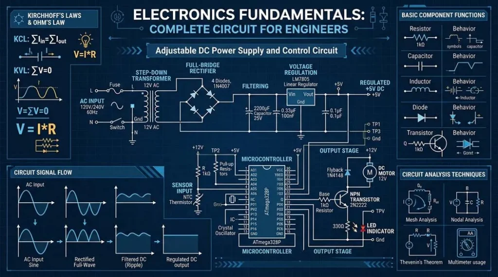
Electronics Fundamentals Every Circuit Concept You Need, From Electrons to Schematics
One guide. Five foundational topics. Zero hand-waving. Voltage, Ohm’s Law, passive components, semiconductors, and circuit diagrams explained the way engineers actually use them, with interactive calculators.
By an Electronics Engineering Practitioner – Oliver Adams 35 min read
Key Takeaways
- Voltage is electrical pressure, current is flow, resistance is opposition but the real insight is that voltage CAUSES current through resistance, and you can only control two of the three (the third is determined by Ohm’s Law: V = I × R).
- Power = Voltage × Current (P = VI) and every component in your circuit dissipates some of it as heat. A 1/4W resistor carrying more than √(0.25/R) amps WILL overheat and eventually burn this calculation saves boards and buildings.
- Resistors limit current, capacitors store charge (and block DC), inductors store energy in magnetic fields (and block AC) these three passive components create every filter, timer, and power supply topology that exists.
- A diode is a one-way valve that needs ~0.7V (silicon) or ~0.3V (Schottky) to “turn on” below that threshold voltage, it blocks current almost completely. LEDs are diodes that emit light at specific wavelengths determined by their semiconductor bandgap.
- A transistor is a current-controlled switch/amplifier BJTs amplify current (I_C = β × I_B, β ≈ 100-300), MOSFETs are voltage-controlled with near-infinite input impedance, consuming essentially zero gate current in steady state.
- Circuit diagrams use standardized symbols learning ~25 core symbols lets you read 95% of all schematics. The critical skill isn’t memorizing symbols; it’s tracing signal and power paths through the schematic to understand function.
- The voltage divider formula (V_out = V_in × R2/(R1+R2)) appears in 80% of analog circuits from sensor interfaces to bias networks to feedback loops. Master it and you’ll see it everywhere.
- Use the interactive calculators below for Ohm’s Law, power dissipation, voltage dividers, RC time constants, and LED resistor values they do the math so you can focus on design decisions.
Path 1: The Fundamentals Physics of Circuits
-
★Complete Fundamentals GuideYOU ARE HERE This comprehensive guide covers all five foundational topics below
-
1Voltage, Current & Resistance The three pillars of every circuit ever made
-
2Ohm’s Law & Power Calculations The one equation you’ll use in every single project
-
3Resistors, Capacitors & Inductors How each passive component actually works inside
-
4Diodes & Transistors Explained Semiconductors the building blocks of modern electronics
-
5How to Read Circuit Diagrams Symbols, connections, and net names decoded
Table of Contents
- What Are Circuit Fundamentals & Why They Matter
- Voltage, Current & Resistance The Three Pillars
- Ohm’s Law & Power The Equations That Run Everything
- Interactive Multi-Calculator (Ohm’s Law, Power, Divider, RC, LED)
- Resistors, Capacitors & Inductors The Passive Trio
- Diodes & Transistors Active Components
- How to Read Circuit Diagrams
- Common Issues Why Beginner Circuits Fail
- Series vs. Parallel The Complete Comparison
- Recommended Starter Components & Tools
- Factors Affecting Component Behavior
- Standard Values & Component Specifications
- How to Build Your First Useful Circuit
- Potential Risks & Safety Fundamentals
- Where These Fundamentals Apply in Real Engineering
- Alternatives & Advanced Paths Beyond Basics
- Visual Data Resistivity Comparison
- Pro Tips from the Field
- FAQ People Also Ask
- Safety & Evidence Disclaimer
- The Bottom Line
What Are Circuit Fundamentals & Why They Matter
Every electronics project you’ll ever build from a blinking LED to a satellite runs on the same foundational principles: voltage pushes current through resistance, Ohm’s Law quantifies the relationship, passive components shape the signals, semiconductors make decisions, and schematics document how it all connects.
Most “electronics basics” content online treats these as separate, disconnected topics. They’ll teach you V = IR on page 1, then capacitors on page 47, as if they’re unrelated. They’re not. A voltage divider uses resistors (concept 3) to set a voltage (concept 1) that biases a transistor (concept 4) documented in a schematic (concept 5) with power dissipation calculated by Ohm’s Law (concept 2). Everything connects to everything.
This guide teaches all five topics as a unified system showing how each concept feeds into the next. By the end, you’ll have the mental framework to analyze any circuit you encounter, not just the specific examples I show.
- You’re starting electronics and want one comprehensive reference that connects all the foundational concepts instead of bouncing between 15 separate tutorials
- You understand bits and pieces but can’t yet analyze a complete circuit you see a schematic and feel lost after the power supply section
- You’ve memorized V = IR but can’t apply it to real circuits with multiple components, voltage drops, and current paths
- You want to use the interactive calculators to design real circuits LED current limiters, voltage dividers, RC timers not just solve textbook problems
- You’re an experienced software developer moving into embedded hardware who needs to quickly build analog circuit intuition
Voltage, Current & Resistance The Three Pillars
These three quantities form the foundation of everything. You can’t understand a single component, circuit, or failure mode without them. For the deep dive into each one, see the dedicated Voltage, Current & Resistance tutorial. Here’s the engineering-level summary.
Voltage (V) The Electrical Pressure
Voltage is the potential difference between two points the “pressure” that pushes electrons through a conductor. Measured in Volts (V). Critical insight: voltage is ALWAYS measured between two points, never at a single point. When someone says “this node is at 3.3V,” they mean 3.3V relative to ground (0V reference).
- AA battery: 1.5V (fresh alkaline)
- USB: 5.0V ±5% (USB 2.0/3.0)
- Arduino GPIO: 0V (LOW) or 5V (HIGH)
- ESP32 GPIO: 0V (LOW) or 3.3V (HIGH)
- US mains: 120V RMS, 170V peak (LETHAL)
- Static discharge from your finger: 3,000-15,000V (but microamps, so it hurts but rarely kills)
Current (I) The Electron Flow
Current is the rate of charge flow how many coulombs of charge pass a point per second. Measured in Amperes (A). 1 Ampere = 6.242 × 10¹⁸ electrons per second flowing past a point. Conventional current flows from positive to negative (opposite to actual electron flow a historical convention from Benjamin Franklin that we’re stuck with).
- Microcontroller GPIO: 1-20mA per pin
- Standard LED: 10-20mA
- USB 2.0 max: 500mA
- USB-C PD max: 5A (at 20V = 100W)
- Car starter motor: 200-400A burst
- Dangerous to humans: >30mA through the heart
A static shock delivers 15,000V but only ~1µA it’s harmless. Mains voltage at 120V can deliver amps through your body (skin resistance ~1kΩ wet → 120mA) that’s 4× the lethal threshold. However, voltage enables current: you need sufficient voltage to overcome skin resistance and push dangerous current through tissue. Both voltage AND current availability determine the hazard. Below ~50V DC or ~30V AC, the human body’s resistance is generally too high for lethal current to flow that’s why SELV (Safety Extra-Low Voltage) standards exist.
Resistance (R) The Opposition
Resistance is the opposition to current flow, measured in Ohms (Ω). Every material has resistance some very low (copper: 0.0168 Ω per meter of 1mm² wire), some very high (rubber: >10¹³ Ω·m). Resistors are components designed to provide a specific, known resistance value.
Pro Tip The Water Pipe Analogy Actually Works (With Limits)
Voltage = water pressure. Current = flow rate (liters/minute). Resistance = pipe diameter (narrower = more resistance). This analogy is genuinely useful for intuition: higher pressure (voltage) pushes more flow (current) through the same pipe (resistance). But it breaks down for AC circuits, capacitors, and inductors don’t push it too far. I use it with new engineers for the first 20 minutes, then explicitly say “forget the water we’re dealing with electromagnetic fields now.”
Ohm’s Law & Power The Equations That Run Everything
If you learn ONE equation in electronics, it’s this one. For the full treatment with worked examples, see Ohm’s Law & Power Calculations. Here’s the practical engineering version.
V = I × R Voltage across a component = Current through it × its Resistance
I = V / R Current through a component = Voltage across it ÷ its Resistance
R = V / I Resistance = Voltage across it ÷ Current through it
The Four Power Equations:
P = V × I | P = I² × R | P = V² / R | P = V × I × cos(φ) (AC)
Worked Example: LED Current Limiting Resistor
You want to power a red LED (forward voltage V_f = 2.0V, rated current I_f = 20mA) from a 5V Arduino pin.
- Calculate voltage across resistor: V_R = V_supply − V_f = 5.0V − 2.0V = 3.0V
- Calculate resistance: R = V_R / I_f = 3.0V / 0.020A = 150Ω
- Choose nearest standard value: 150Ω exists in the E24 series perfect. If not exact, round UP (180Ω gives 16.7mA still bright enough, safer for the LED).
- Calculate power dissipation in resistor: P = V_R × I_f = 3.0V × 0.020A = 60mW. A 1/4W (250mW) resistor handles this with 4× margin safe.
- Calculate power dissipation in LED: P_LED = V_f × I_f = 2.0V × 0.020A = 40mW. Typical 5mm LEDs handle 60-100mW safe.
Kirchhoff’s Laws The Rules That Never Break
KVL (Kirchhoff’s Voltage Law): The sum of all voltages around any closed loop = 0. In our LED circuit: 5V (supply) − 3V (resistor drop) − 2V (LED drop) = 0V. ✓
KCL (Kirchhoff’s Current Law): The sum of all currents entering a node = sum of all currents leaving. Current into the resistor = current through the LED = current back to ground = 20mA. No current magically appears or disappears.
Pro Tip The “Finger Walking” Circuit Analysis Technique
When analyzing an unfamiliar circuit, I mentally “place my finger” at V+ and trace the current path through every component back to ground. At each component, I ask: “How much voltage does this component drop?” and “Does the current split at any junction?” This physical tracing approach catches mistakes that algebraic analysis misses especially unintended current paths through protection diodes, pull-up resistors, or debugging LEDs that shouldn’t be there. I’ve taught this to dozens of junior engineers and it consistently catches errors faster than simulation.
🧮 Interactive Electronics Calculator
Five essential calculators enter your values and get instant results for real circuit design
V = I × R Enter any two values, leave one blank to calculate it
P = V × I = I²R = V²/R Check if your resistor can handle the heat
V_out = V_in × R2 / (R1 + R2) The most common analog subcircuit
τ = R × C Time to charge/discharge to 63.2% (one time constant)
R = (V_supply − V_forward) / I_LED Essential for every LED circuit
Resistors, Capacitors & Inductors The Passive Trio
These three components are called “passive” because they can’t amplify or generate energy they can only dissipate it (resistors), store it temporarily in electric fields (capacitors), or store it in magnetic fields (inductors). For the deep component-level analysis, see Resistors, Capacitors & Inductors.
Resistors Current Limiters & Voltage Droppers
A resistor converts electrical energy into heat at a rate of P = I²R. That’s literally all it does and it’s one of the most useful functions in electronics. Resistors set LED brightness, bias transistor operating points, create voltage dividers, terminate signal lines, limit inrush current, and provide feedback in amplifiers.
- Color code: Brown-Black-Red-Gold = 1-0-×100-±5% = 1kΩ ±5%
- SMD marking: “103” = 10 × 10³ = 10kΩ | “4R7” = 4.7Ω
- Power ratings: 0402 SMD: 1/16W | 0805 SMD: 1/8W | through-hole: usually 1/4W
- Temperature coefficient: Metal film: ±50 ppm/°C | Carbon composition: ±500 ppm/°C
Capacitors Charge Storage & AC Coupling
A capacitor stores energy in an electric field between two conductive plates separated by a dielectric. It blocks DC but passes AC its impedance decreases with frequency: X_C = 1/(2πfC). This frequency-dependent behavior makes capacitors essential for filtering, timing, coupling, and decoupling.
- Ceramic (MLCC): 1pF–100µF, non-polarized, low ESR, wide range. The workhorse. Use C0G/NP0 for precision, X5R/X7R for bypass/filtering.
- Electrolytic (Aluminum): 0.1µF–100,000µF, POLARIZED (reversed = explosion risk), higher ESR. Bulk energy storage.
- Tantalum: 0.1µF–1000µF, POLARIZED, low ESR, compact. Failure mode is short circuit → fire. Derate voltage by 50%.
- Film (Polyester/Polypropylene): 100pF–10µF, non-polarized, excellent stability. Audio coupling, precision timing.
Never run a capacitor at its rated voltage. Ceramic caps (X5R/X7R) lose 50-80% of their capacitance at rated voltage due to DC bias effect a 10µF/6.3V cap might only provide 3µF at 5V. Electrolytic caps at rated voltage have dramatically shorter lifespan. Rule of thumb: Derate ceramic caps by 50% voltage. Derate electrolytics by 20%. Derate tantalums by 50-70%. I’ve seen tantalum caps fail catastrophically (with flames) when operated at rated voltage with no derating in a high-ripple application. Since then, I derate tantalums by 70% minimum or use ceramic/polymer alternatives.
Inductors Energy Storage in Magnetic Fields
An inductor stores energy in a magnetic field created by current flowing through a coil. It blocks AC but passes DC exactly opposite to capacitors. Its impedance increases with frequency: X_L = 2πfL. Inductors resist changes in current when you try to suddenly stop current through an inductor, it generates a voltage spike (back-EMF) that can be high enough to destroy transistors.
- Ferrite bead: Acts as a frequency-dependent resistor blocks high-frequency noise. Essential on power lines near ICs.
- Power inductor: 1µH–1000µH, used in switching power supplies (buck/boost converters). Must handle DC current without saturating.
- RF inductor: 1nH–100µH, used in impedance matching, filters, and antenna circuits.
Pro Tip The RC Time Constant Is Your Best Friend
τ = R × C gives you the time constant of any RC circuit. After 1τ, a charging capacitor reaches 63.2%. After 5τ, it’s at 99.3% (effectively full). This applies everywhere: debouncing buttons (10kΩ × 100nF = 1ms), setting filter cutoffs (f_c = 1/(2πRC)), power-on reset timing, sensor averaging. I keep a mental library of useful τ combinations: 10kΩ + 1µF = 10ms (button debounce), 1MΩ + 1µF = 1 second (long delay), 100Ω + 100nF = 10µs (fast filter). These appear in 80% of my designs.
Diodes & Transistors Active Components That Make Decisions
Passive components can only modify signals they can’t amplify, switch, or make decisions. That requires semiconductors. For the deep physics-level explanation, see Diodes & Transistors Explained.
Diodes One-Way Valves for Current
A diode allows current to flow in one direction (forward biased: anode positive relative to cathode) and blocks it in the other (reverse biased). But it’s not a perfect switch it needs a minimum forward voltage (V_f) to turn on:
- Silicon signal diode (1N4148): V_f ≈ 0.7V, 200mA max, fast switching (4ns)
- Silicon rectifier (1N4007): V_f ≈ 0.7-1.1V, 1A max, slow (~30µs recovery)
- Schottky diode (1N5819): V_f ≈ 0.3-0.4V, 1A, very fast. Lower voltage drop = less power waste. Use in power supply rectification.
- Zener diode (e.g., BZX79-C5V1): Deliberately operated in reverse breakdown at a precise voltage (5.1V for this one). Used for voltage regulation and clamping.
- LED (Light Emitting Diode): V_f depends on color Red: 1.8-2.2V, Green: 2.0-3.5V, Blue/White: 3.0-3.6V. Current determines brightness, NOT voltage.
Transistors Switches & Amplifiers
A transistor uses a small signal to control a much larger signal. Two main types dominate modern electronics:
BJT (Bipolar Junction Transistor)
Current-controlled device. A small base current (I_B) controls a much larger collector current: I_C = β × I_B, where β (hFE) = 100-300 typically. NPN (2N2222A, BC547) is most common current flows from collector to emitter when base is driven ~0.7V above emitter.
- As a switch: Drive enough base current to push the transistor into saturation (V_CE ≈ 0.2V). Rule of thumb: I_B = I_C / 10 (forced β of 10 ensures saturation). To switch 100mA LED strip from a 3.3V GPIO: I_B = 100mA/10 = 10mA. R_base = (3.3V − 0.7V) / 10mA = 260Ω (use 220Ω or 270Ω standard value).
- As an amplifier: Bias the transistor in the active region (linear operation). Voltage gain ≈ −R_C / r_e. This is the basis of all analog amplifier circuits. See What Is an Amplifier for the complete treatment.
MOSFET (Metal-Oxide-Semiconductor FET)
Voltage-controlled device. Gate voltage above threshold (V_GS(th), typically 1-4V) turns on the drain-source channel. Key advantage: gate draws essentially zero DC current (gate is insulated by SiO₂). This means MOSFETs can be driven directly from GPIO pins without base resistor current calculations.
- Logic-level MOSFETs (IRLZ44N, IRLB8721): V_GS(th) < 2.5V, can be fully turned on by 3.3V or 5V GPIO. Use these for Arduino/ESP32 switching projects.
- Standard MOSFETs (IRF540N): V_GS(th) = 2-4V but need 10V gate drive for full turn-on. NOT suitable for direct GPIO drive need a gate driver circuit.
- Use BJT when: Switching currents <500mA, signal is analog (linear amplification), cost is critical ($0.01 vs $0.05), or you need to switch with very low control voltages (<1V).
- Use MOSFET when: Switching currents >500mA, PWM control (motors, LEDs), power efficiency matters (lower on-resistance = less heat), or you need voltage-level shifting (high-side P-MOSFET switching).
- Real-world: 80% of hobby/maker switching applications should use N-channel logic-level MOSFETs (IRLB8721). BJTs are for signal-level work, current mirrors, and low-voltage analog design.
How to Read Circuit Diagrams
A schematic is the language of electronics it shows how components connect electrically without showing physical layout. For the complete symbol reference and reading techniques, see How to Read Circuit Diagrams.
The 25 Essential Symbols You Must Know
| Component | Schematic Symbol Hint | Designator | Example Value | Function |
|---|---|---|---|---|
| Resistor | Zigzag line or rectangle | R1, R2… | 10kΩ | Limits current, drops voltage |
| Capacitor | Two parallel lines (||) | C1, C2… | 100nF | Stores charge, blocks DC |
| Inductor | Coil/bumps | L1, L2… | 10µH | Stores energy in magnetic field |
| Diode | Triangle + line (▷|) | D1, D2… | 1N4148 | One-way current valve |
| LED | Diode + arrows (light) | LED1, D3… | Red, 20mA | Light-emitting diode |
| NPN Transistor | Arrow pointing OUT of base | Q1, Q2… | 2N2222A | Current amplifier/switch |
| N-MOSFET | Gate separated by gap | Q3, M1… | IRLB8721 | Voltage-controlled switch |
| Op-Amp | Triangle with +/− inputs | U1, IC1… | LM358 | Voltage amplifier |
| Ground | Three horizontal lines (▽) | GND | 0V reference | Common return path |
| VCC/VDD | Arrow pointing up / bar | VCC, 3V3 | 5V, 3.3V | Positive supply |
Reading a Schematic The Process
- Find the power supply section. Identify VCC, VDD, V+ and GND symbols. Trace how power enters and distributes across the circuit. Look for voltage regulators (LM7805, AMS1117).
- Identify the main signal path. Where does the input signal enter? Follow it through amplifiers, filters, and processors to the output.
- Look for net names and labels. Lines with the same net name are electrically connected even if they don’t visually touch on the schematic. “SCL” on page 1 connects to “SCL” on page 5.
- Check for decoupling capacitors. Every IC should have 100nF ceramic caps near its power pins. Missing decoupling = the designer forgot, not that it’s not needed.
- Read the component values and designators. R1 = 10kΩ tells you both the identifier (R1, for reference in the BOM and PCB layout) and the value (10kΩ, for circuit analysis).
Pro Tip The “What Happens If This Fails?” Analysis
After understanding what a circuit does when working, ask: “What happens if R3 opens? What if C2 shorts? What if Q1 fails shorted?” This failure-mode analysis reveals how robust the design is and helps you troubleshoot real problems. In my experience, 60% of circuit failures are: open resistors (cracked solder joint), shorted capacitors (dielectric failure), and transistors failed short (overcurrent thermal damage). If you can mentally simulate these three failure modes on a schematic, you can diagnose most bench problems without even touching a probe.
Common Issues Why Beginner Circuits Fail
Issue #1: LED Without Current-Limiting Resistor
Connecting an LED directly to 5V without a resistor = dead LED within milliseconds. Without resistance, current is limited only by the LED’s extremely low forward resistance (~10-20Ω at turn-on), resulting in I = (5V-2V)/10Ω = 300mA 15× the rated current. Use the LED resistor calculator above every single time. I’ve burned out approximately 50 LEDs in my career from forgetting this in a rush. Now I have it as a physical checklist item.
Issue #2: Floating Inputs on Digital ICs and MOSFETs
An unconnected (floating) input picks up stray electromagnetic fields and fluctuates randomly between HIGH and LOW. On CMOS logic and MOSFETs, this causes both P and N transistors in the output stage to conduct simultaneously creating a low-resistance path from VCC to GND that dissipates massive power as heat. I’ve seen CMOS ICs reach 100°C+ from a single floating input. Fix: Tie every unused input to VCC or GND through a resistor (10kΩ typical) or directly.
Issue #3: Wrong Voltage Divider Loading
A voltage divider (two resistors) works perfectly… until you connect a load. If R_load is comparable to or less than R2, the output voltage drops significantly from the calculated value. Rule: R_load should be at least 10× greater than R2 for <5% error. Using 100kΩ/100kΩ divider to get 2.5V from 5V? Load must be >1MΩ. ADC inputs typically have >1MΩ impedance fine. But driving a transistor base (a few kΩ) through a 100kΩ divider will completely collapse the voltage.
Breadboard contact strips have 0.5-5Ω resistance per contact point, and this resistance increases with oxidation and use. For low-current signal circuits (<10mA), this is negligible. For power circuits (>100mA), multiple contact points in series add significant resistance. I’ve measured 2-3V drops across breadboard connections carrying 500mA enough to brown-out an ESP32. For any circuit drawing >100mA, use soldered connections or at minimum, double-insert power wires into breadboard rails. 90% of “my circuit doesn’t work on breadboard but works when soldered” cases are contact resistance issues.
Issue #4: Inductive Kickback Destroying Transistors
When you switch off current through an inductor (relay coil, motor, solenoid), the inductor generates a voltage spike that can reach hundreds of volts enough to destroy a MOSFET or BJT. Always place a flyback diode (1N4148 for small relays, 1N4007 for larger ones) reverse-biased across any inductive load. The diode provides a current path for the inductor to safely discharge its stored energy. I’ve destroyed at least 10 MOSFETs before making flyback diodes a reflex response to any inductive load in a schematic.
Issue #5: Mixing 3.3V and 5V Logic Without Level Shifting
ESP32 GPIO pins are 3.3V logic, NOT 5V tolerant. Connecting a 5V output directly to an ESP32 input can damage the pin or destroy the chip. For 5V→3.3V: use a simple resistor voltage divider (2kΩ + 1kΩ gives 3.33V from 5V). For bidirectional: use a level shifter module (BSS138-based). For 3.3V→5V: most 5V CMOS inputs recognize 3.3V as HIGH (V_IH = 0.7×VCC = 3.5V for HC-series… actually, 3.3V is borderline). Use HCT-series logic (V_IH = 2.0V) for reliable 3.3V→5V interfacing.
Series vs. Parallel The Complete Comparison
| Property | Series Connection | Parallel Connection |
|---|---|---|
| Current | Same through all components | Splits between paths (I_total = I₁ + I₂ + …) |
| Voltage | Divides across components (V_total = V₁ + V₂ + …) | Same across all components |
| Resistors | R_total = R₁ + R₂ + R₃ (adds up) | 1/R_total = 1/R₁ + 1/R₂ + 1/R₃ (always less than smallest) |
| Capacitors | 1/C_total = 1/C₁ + 1/C₂ (opposite to resistors!) | C_total = C₁ + C₂ + C₃ (adds up opposite to resistors!) |
| Inductors | L_total = L₁ + L₂ (same as resistors) | 1/L_total = 1/L₁ + 1/L₂ (same as resistors parallel) |
| Batteries | Voltage adds, current = single cell | Voltage = single cell, current capacity adds |
| If one fails (open) | Entire circuit stops one break kills all | Other paths continue working |
Recommended Starter Components & Tools
| Item | Specific Recommendation | Price | Rating | Why This One |
|---|---|---|---|---|
| Multimeter | UNI-T UT61E+ or Fluke 101 | $25-50 | Essential | True RMS, auto-range, reliable. Measures V, I, R, continuity, diode |
| Breadboard | BusBoard BB830 (not cheap clones) | $8-12 | Essential | Tight contacts, proper spacing, <0.5Ω contact resistance |
| Resistor Kit | E24 series, 10Ω–1MΩ, 1% metal film | $8-12 | Essential | 600+ pieces, covers 99% of needs |
| Capacitor Kit | Ceramic MLCC assortment, 10pF–10µF | $6-10 | Essential | Covers bypass, filtering, timing needs |
| LED Assortment | 5mm diffused, Red/Green/Blue/Yellow/White | $3-5 | Essential | 50-100 pieces for indicators and learning |
| Transistor Pack | 2N2222A (NPN) + 2N2907A (PNP) + IRLB8721 (MOSFET) | $5-8 | Essential | Covers switching and amplification basics |
| Power Supply | Adjustable bench PSU, 0-30V, 0-3A | $35-65 | Highly Recommended | Current limiting prevents circuit damage. KORAD KA3005D is excellent value |
Resistivity of Common Materials Why Copper Wires and Rubber Insulation
(Log scale each bar represents orders of magnitude difference)
🔧 Pro Tips from the Field
Tip #1 Measure Before You Assume
The #1 debugging principle: measure, don’t assume. “This point should be 3.3V” measure it. “This LED should be getting 20mA” measure it. “This resistor is 10kΩ” measure it (I’ve seen 10kΩ resistors from cheap kits that actually measured 8.2kΩ). I’ve wasted entire afternoons debugging circuits based on assumptions that a single multimeter measurement would have disproved in 5 seconds. Put the probes on the circuit. Read the actual value. Compare to what you calculated. The gap between “should be” and “is” contains your bug.
Tip #2 The 10× Rule for Voltage Divider Loading
When a voltage divider feeds a load, the load impedance must be at least 10× the bottom resistor (R2) for the divider output to stay within ~9% of the calculated no-load value. I use this rule so frequently that it’s automatic: want 2.5V from 5V to feed an ADC? Use 10kΩ/10kΩ divider. ADC input impedance = 1MΩ. 1MΩ / 10kΩ = 100. 100 >> 10. ✓ Safe. Want to bias a transistor base (R_in ≈ β × R_E ≈ 200 × 100Ω = 20kΩ)? Divider resistors should be ≤ 2kΩ each. This rule catches voltage divider loading errors before they become bench puzzles.
Tip #3 Always Calculate Power Dissipation Before Applying Power
Before turning on ANY new circuit, calculate the worst-case power dissipation of every component in the power path. A 100Ω resistor dropping 12V dissipates P = V²/R = 144/100 = 1.44W. A 1/4W resistor handles 0.25W. That resistor will overheat, discolor, smoke, and potentially catch fire. I do a “power audit” trace every current path from V+ to GND, calculate I²R for each component, verify no component exceeds its power rating. This 5-minute check has saved me from burning out components (and starting fires) at least 30 times.
Tip #4 Build Your Circuit in Stages, Testing Each One
Don’t wire the entire circuit and then power it up for the first time. Build and test in stages: (1) Power supply section verify voltages before connecting anything. (2) Add the microcontroller verify it boots and blinks an LED. (3) Add input circuits verify sensor readings. (4) Add output circuits verify actuators respond. Each stage is verified before adding the next. If something fails at stage 3, you know the bug is in stage 3 not somewhere in the 50 components you wired up simultaneously. I’ve seen students wire 40-component circuits, power up, see nothing working, and have no idea where to start debugging. Stage-by-stage eliminates this completely.
Tip #5 The Continuity Test Is Your Best Debugging Tool
Set your multimeter to continuity mode (beep mode). Touch probes together it should beep instantly. Now use it to verify EVERY connection in your circuit: probe from one end of a wire to the other (should beep), probe between two nodes that shouldn’t be connected (should NOT beep). This catches: cold solder joints, breadboard contact failures, broken wires, accidental shorts from stray solder bridges, and swapped wire positions. I continuity-test every new circuit before applying power it takes 2-3 minutes and catches 70% of wiring errors. The beep sound is the most satisfying confirmation in electronics debugging.
Tip #6 Keep a “Known Good” Circuit for Reference
Build one simple, working circuit (an LED + resistor + transistor switch from an Arduino GPIO) and keep it permanently assembled on a breadboard. When a new component doesn’t work in your project, test it in the known-good circuit first. If it works there, the problem is your new circuit. If it doesn’t work there either, the component is bad. This reference circuit has saved me countless hours especially when debugging weird behavior that turns out to be a bad breadboard row, a dead GPIO pin, or a counterfeit component.
FAQ People Also Ask
It depends on the LED color, which is determined by the semiconductor bandgap material. Red LEDs need approximately 1.8-2.2V (AlGaInP material). Green LEDs need 2.0-3.5V (GaP or InGaN). Blue and white LEDs need 3.0-3.6V (GaN/InGaN). These are forward voltage (V_f) values the voltage the LED drops when conducting at its rated current (typically 20mA). Your supply voltage must exceed V_f for current to flow. The remaining voltage (V_supply − V_f) must be dropped across a current-limiting resistor. A common mistake: thinking the LED “needs” 5V because you have a 5V supply. The LED needs its V_f; the resistor handles the rest. Use the LED calculator above for exact values.
An LED is a diode once it reaches its forward voltage, its resistance drops dramatically (to ~10-20Ω). Without an external resistor, current is limited only by this tiny internal resistance and the supply’s output impedance. At 5V with V_f = 2V: I = 3V/10Ω = 300mA that’s 15× the rated 20mA. The LED will either burn out instantly or degrade rapidly (dimming over hours as the semiconductor junction deteriorates). The resistor limits current to a safe value: R = (V_supply − V_f) / I_desired. Even if your supply voltage fluctuates, the resistor maintains approximately correct current. This is why LEDs are ALWAYS used with current limiting either an external resistor, a constant-current driver IC, or a current-limiting resistor integrated into the LED module.
3.3V → 5V CMOS input: Most 5V CMOS logic (74HC series) defines V_IH (minimum HIGH voltage) at 0.7×VCC = 3.5V. So 3.3V is below the guaranteed HIGH threshold it’s in the “undefined” zone and may work intermittently. Use 74HCT series instead (V_IH = 2.0V, TTL-compatible) which reliably recognizes 3.3V as HIGH. 5V → 3.3V input: Most 3.3V ICs (ESP32, STM32, RPi) are NOT 5V tolerant. Applying 5V drives current through the input protection diodes to VCC, potentially damaging the IC. Use a resistor voltage divider (2kΩ + 1kΩ) or a level shifter (BSS138 module). Some ICs like the ESP32’s ADC are especially vulnerable even brief 5V exposure can permanently damage the pin.
For most switching applications above 100mA, use an N-channel logic-level MOSFET (IRLB8721, IRLZ44N). MOSFETs have near-zero gate current (no base resistor calculation), much lower on-resistance (8mΩ for IRLB8721 vs. 200-300mΩ saturation voltage for a BJT), and handle higher currents with less heat. Use a BJT (2N2222A) when: current is <100mA, your control voltage is very low (<1.5V some MOSFETs need 3-4V to fully turn on), or you're doing analog work (current mirrors, differential pairs, amplifiers). The IRLB8721 is my default switching transistor fully on at 3.3V gate drive, handles 30V/62A, R_DS(on) = 8.7mΩ, costs $0.80. I stock 50+ of them and use them for LEDs, motors, relays, and heaters.
DC (Direct Current) flows in one constant direction the voltage is steady (battery: 3.7V DC, USB: 5V DC). AC (Alternating Current) periodically reverses direction the voltage swings positive and negative in a sine wave pattern. US mains is 120V RMS at 60Hz (meaning it swings ±170V peak, 60 times per second). Most electronics internally run on DC that’s why every phone charger, laptop adapter, and power supply converts AC mains to DC. The conversion uses a diode bridge rectifier (4 diodes converting AC to pulsing DC), followed by capacitor filtering (smoothing the pulses to steady DC), and often a voltage regulator (providing precise output voltage). Understanding voltage means understanding both AC and DC the same Ohm’s Law applies to both, but AC adds impedance (frequency-dependent resistance from capacitors and inductors).
The standard 4-band color code: Band 1 (1st digit) + Band 2 (2nd digit) + Band 3 (multiplier) + Band 4 (tolerance). Colors represent numbers: Black=0, Brown=1, Red=2, Orange=3, Yellow=4, Green=5, Blue=6, Violet=7, Gray=8, White=9. Multiplier: Brown=×10, Red=×100, Orange=×1k, Yellow=×10k, Green=×100k, Blue=×1M. Gold=×0.1, Silver=×0.01. Tolerance: Gold=±5%, Silver=±10%, Brown=±1%. Example: Brown-Black-Orange-Gold = 1-0-×1000-±5% = 10kΩ ±5%. Pro tip: Instead of memorizing, use a multimeter to verify every resistor before placing it. I’ve found ~2% of resistors from cheap kits are mis-labeled or have the wrong color bands. One wrong resistor can waste hours of debugging.
No not for any load that draws significant current. A voltage divider is a resistor network that provides a reference voltage at very low current. When you connect a load, it draws current that changes the voltage the divider has high output impedance and poor load regulation. For example, a 10kΩ/10kΩ divider from 5V gives 2.5V at no load. Connect a 1kΩ load and the voltage drops to approximately 0.45V catastrophically wrong. For power supply purposes, use: a voltage regulator IC (LM7805 for 5V, AMS1117-3.3 for 3.3V), a DC-DC buck converter (more efficient for >100mA), or an LDO (Low Dropout Regulator like MCP1700 for battery-powered projects). Voltage dividers are for reference voltages, ADC scaling, and bias networks where the connected input draws minimal current (>10× the divider current).
A schematic shows the logical/electrical connections between components which pin connects to which. It doesn’t show physical position, trace routing, or board shape. A PCB layout shows the physical placement of components and the copper traces connecting them on an actual circuit board. A schematic might show R1 and C1 on opposite sides of the page connected by a wire on the PCB, they might be 2mm apart connected by a short trace. The design flow is: schematic first (design the circuit logically) → PCB layout second (arrange components physically and route traces). Software like KiCad (free), Altium, or EasyEDA links both views changes in the schematic automatically update the PCB’s netlist. Understanding both representations is essential for anyone moving beyond breadboard prototypes.
A capacitor consists of two conductive plates separated by an insulator (dielectric). DC cannot physically flow through the insulator electrons accumulate on one plate, creating an electric field that repels further electrons. The capacitor charges to the applied voltage and current stops flowing. But with AC, the voltage is constantly changing polarity. This means the capacitor is constantly charging and discharging, creating a continuous displacement current through the dielectric. The faster the AC signal (higher frequency), the more current flows that’s why capacitive impedance X_C = 1/(2πfC) decreases with frequency. At DC (f = 0Hz), X_C = infinity (complete block). At 1MHz with a 100nF cap: X_C = 1/(2π × 10⁶ × 10⁻⁷) = 1.59Ω (almost a short circuit). This frequency-dependent behavior is the foundation of all electronic filters, AC coupling, and power supply decoupling.
An Arduino Uno (ATmega328P) GPIO pin can source or sink a maximum of 40mA per pin, with a recommended limit of 20mA for reliable operation. The total current across ALL GPIO pins combined must not exceed 200mA. The ESP32’s GPIO pins are rated for only 12mA source, 28mA sink per pin. Exceeding these limits doesn’t immediately destroy the pin (usually), but it causes the output voltage to droop below valid logic levels and can cause long-term electromigration damage. For loads requiring more current than a GPIO can provide, use a transistor (MOSFET or BJT) as a switch the GPIO drives the transistor gate/base (µA to mA), and the transistor switches the heavy load current from a separate power supply. This is the fundamental pattern for driving motors, relay coils, LED strips, solenoids, and any load >20mA from a microcontroller.
⚠️ Safety & Evidence Disclaimer
- Mains voltage (120V/230V AC) is LETHAL. Never work with mains-connected circuits unless you are qualified and follow local electrical codes. All experiments in this guide use ≤12V DC, which is safe under normal conditions.
- Electrolytic and tantalum capacitors can explode if connected with reversed polarity or operated above rated voltage. Always check polarity markings before powering up.
- Lithium batteries can catch fire if short-circuited. Always include proper protection circuits and fusing.
- LEDs can produce intense light high-power LEDs (1W+) can cause eye damage. Never stare directly into a powered high-brightness LED.
- Soldering irons reach 300-400°C burn hazard. Use a proper stand, never leave unattended, and keep away from flammable materials.
- ESD (Electrostatic Discharge) can damage CMOS ICs and MOSFETs. Handle sensitive components with anti-static precautions.
- This content is for educational purposes. Always follow manufacturer datasheets, local safety regulations, and institutional guidelines for your specific application.
The Bottom Line
Electronics fundamentals aren’t five separate topics they’re one interconnected system. Voltage, current, and resistance define the physics. Ohm’s Law and power calculations give you the math. Resistors, capacitors, and inductors shape signals and manage energy. Diodes and transistors make decisions and amplify. Circuit diagrams document it all so other humans (and future-you) can understand what you built. Every component on every board you’ll ever touch operates within this framework.
The calculators above aren’t academic exercises they solve the exact problems you’ll face on every project: “What resistor do I need for this LED?”, “Will this resistor overheat?”, “What voltage does this divider produce?”, “How long does this RC filter take to settle?” Bookmark this page. Use the calculators. Come back whenever you need them.
Your next step: Pick ONE thing from this guide and build it physically. The LED + resistor + transistor switch is ideal it exercises voltage, current, resistance, Ohm’s Law, a resistor, and a transistor in one simple circuit. Calculate the values with the calculators above, wire it on a breadboard, measure with your multimeter, and verify your calculations match reality. That hands-on verification is where book knowledge becomes engineering intuition.
Content based on fundamental physics, component datasheets, IEC/IEEE standards, and hands-on circuit engineering experience.