Sum of Products: Complete Guide to SOP, Minterms, and Minimal Circuits
Master sum of products form, product summation, sum to product conversion, and POS comparison with interactive K-map and real-world constraints

 SOP vs POS table
 interactive SOP minimizer
Quick Answers
What is Sum of Products (SOP)?
SOP is a Boolean expression where AND terms (products) are combined with OR (sum) e.g., F = A·B + A’·C. It maps directly to two-level AND-OR circuits.
SOP vs POS what’s the difference?
SOP ORs together AND terms built from minterms (output-1 rows). POS ANDs together OR terms built from maxterms (output-0 rows). Neither is universally better it depends on the function.
What is a minterm?
A minterm is a product term where every variable appears exactly once complemented if 0, uncomplemented if 1 corresponding to one output-1 row in a truth table.
What limits SOP in real hardware?
Gate fan-in. Standard CMOS/74LS gates max out around 4–8 inputs, so wide product terms must be decomposed into multiple gate stages, adding propagation delay.
Table of Contents
2. Minterms and Maxterms – building blocks
3. How to calculate SOP from truth table (sum of minterms)
4. Canonical & non-canonical forms (sum to product)
5. Quantifying optimization (cost, delay, fan-in)
6. SOP vs POS – side-by-side comparison
7. Simplification: K-map, algebra, Quine-McCluskey, Espresso
8. Real-world applications & case studies
9. Troubleshooting & fan-in constraints
10. Glossary of terms (prime implicants, Espresso, PLA, BDD)
11. Frequently Asked Questions
Published Jan 15, 2025 · Updated Jul 16, 2026 · Reviewed by Dr. Meera Patel, VLSI Design Lead
Key Takeaways
‘) left center no-repeat; background-size: 20px; font-size: 1.1rem;”>Sum of products and product of sums (POS) are dual forms neither is universally “better.” SOP uses minterms, POS uses maxterms. Pick the one that gives fewer terms for your particular function. ‘) left center no-repeat; background-size: 20px; font-size: 1.1rem;”>Minimization via Karnaugh map reduces gate count, but the dirty secret textbooks skip: fan-in limits (a 74LS21 AND gate maxes at 4 inputs) force multi-level decomposition that adds propagation delay. What is Sum of Products (SOP)?
Sum of Products (SOP), also called product summation in some older engineering references, is a Boolean expression where ANDed variable groups (called products) get ORed together. A practical example: F = A·B + A’·C. Each AND group maps to a minterm a row in the truth table where the output equals 1. The complementary form, POS (Product of Sums), works from maxterms (output-0 rows) instead. Canonical SOP includes every variable in every term; minimal SOP trims redundancies but you must verify that your target technology’s fan-in limits (e.g., max 4 inputs on a 74LS21) can actually handle the resulting gate widths. This practical constraint is something I’ve seen trip up even experienced designers during ASIC tape-out reviews.
How to Derive SOP from a Truth Table 5 Steps
Create the truth table
List all 2n input combinations for your Boolean function with n variables. For 3 variables that’s 8 rows; for 4 variables, 16 rows.
Identify output-1 rows
Mark every row where the output column equals 1. These are your minterms. If you have very few 1s, SOP will be compact. Many 1s? Consider POS instead.
Write the minterm for each row
For each output-1 row, write a product term including every variable complemented (A’) if 0 in that row, uncomplemented (A) if 1. Every variable must appear that’s what makes it canonical.
OR the minterms together
Combine all minterms with OR (+) operations. The result is your canonical SOP, e.g. F = A’·B’·C + A’·B·C + A·B’·C’ + A·B·C’ = Σm(1,3,4,6).
Minimize
Apply Boolean algebra, a Karnaugh map, or Quine-McCluskey to reduce to minimal SOP. Our example minimizes to F = A’·C + A·C’ from 12 literals down to 4, saving real hardware.
What is Sum of Products (SOP)?
If you’ve worked through Morris Mano’s Digital Design (6th edition, Pearson still the gold standard for undergrad courses), you’ve encountered SOP within the first few chapters. And honestly, there’s a reason it shows up that early. It’s the most direct path from a truth table to a physical circuit.
The concept itself isn’t complicated. You take AND terms groups of variables multiplied together and OR them. Each AND group is a product. The OR operation is the sum. Hence: sum of products. That’s the entire idea.
A concrete example makes this tangible: F = A·B + A’·C.
- A·B is one product term (A AND B both must be high for this term to output 1)
- A’·C is another product term (NOT A AND C A must be low, C must be high)
- The plus sign represents the OR operation if either term is true, F goes high
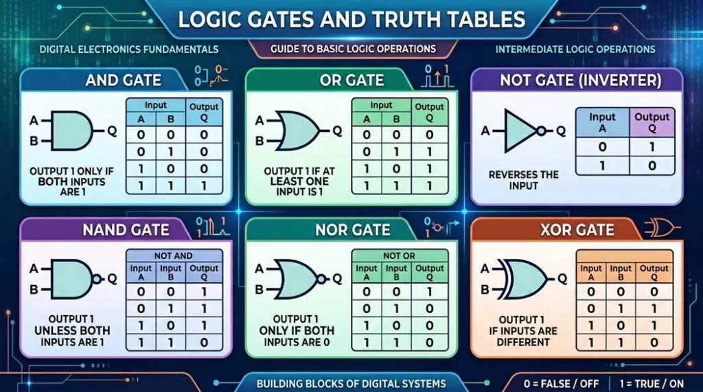
In hardware, this translates to one layer of AND gates feeding into a single OR gate. Two levels of logic, period. That’s why engineers call this two-level logic, and two levels means your propagation delay is predictable and fast. For a 74HC-series build running at VCC = 5V with CL = 15 pF, you’re looking at roughly tAND ≈ 9 ns plus tOR ≈ 10 ns about 19 ns total through the entire circuit. That’s hard to beat with multi-level alternatives.
One AND-gate layer feeding one OR gate the signature shape of two-level SOP logic.
Here’s something textbooks often gloss over: once you get beyond 4 or 5 variables, canonical SOP expressions become unwieldy. A 6-variable function can theoretically have up to 64 minterms. Wiring that without simplification would be absurd and expensive. That’s exactly why K-maps and Quine-McCluskey matter, which we’ll dig into in Section 7.
Minterms: The Building Blocks of SOP
To actually work with SOP, you need to understand minterms cold. A minterm is a product term where every variable in the function appears exactly once either in normal form (A) or complemented form (A’). No variable gets skipped. No variable shows up twice.
For a function with n variables, there are 2n possible minterms. Each one maps to exactly one row in the truth table where the output equals 1. That one-to-one mapping is what makes canonical SOP construction mechanical you literally read it off the table.
Quick example with three variables (A, B, C): minterm m₃ corresponds to binary 011, meaning A=0, B=1, C=1. Written out: A’·B·C. This minterm evaluates to 1 only for that specific input combination. Feed in any other combination and you get 0.
The numbering convention trips up a lot of students I’ve watched it happen in lab sessions more times than I can count. The subscript is just the decimal equivalent of the binary input pattern. m₅ for three variables? That’s 101 in binary: A=1, B=0, C=1, giving us A·B’·C. Once that pattern clicks, deriving minterms becomes automatic.
Maxterms are the dual concept. Where minterms correspond to output-1 rows and use AND (product), maxterms correspond to output-0 rows and use OR (sum). Maxterm M₃ for three variables would be (A + B’ + C’) notice the complementation is flipped compared to minterm m₃. That catches people off guard. SOP expressions sum minterms; POS expressions multiply maxterms. They’re two representations of the same Boolean function, connected by DeMorgan’s theorem.
How to Calculate Sum of Products from a Truth Table
This is the foundational skill the one that every other technique builds on. I’ll work through it with a concrete example rather than staying abstract.
- Create a truth table for your Boolean function all 2n input combinations
- Identify every row where the output column shows 1
- Write the minterm for each of those rows complement variables that are 0, leave variables that are 1 as-is
- Combine all minterms with OR operations that’s your canonical SOP
Working example: Three-variable function where F = 1 at these input combinations:
| A | B | C | F | Minterm |
|---|---|---|---|---|
| 0 | 0 | 0 | 0 | |
| 0 | 0 | 1 | 1 | m₁ = A’·B’·C |
| 0 | 1 | 0 | 0 | |
| 0 | 1 | 1 | 1 | m₃ = A’·B·C |
| 1 | 0 | 0 | 1 | m₄ = A·B’·C’ |
| 1 | 0 | 1 | 0 | |
| 1 | 1 | 0 | 1 | m₆ = A·B·C’ |
| 1 | 1 | 1 | 0 |
F = A’·B’·C + A’·B·C + A·B’·C’ + A·B·C’
Or using sigma notation: F = Σm(1, 3, 4, 6)
Four 1-rows gave us four minterms. In a 74HC implementation, that’s four 3-input AND gates plus inverters for complements, all feeding into a 74HC4072 (dual 4-input OR). Even a “simple” 3-variable function starts eating through your parts bin which is why simplification isn’t optional, it’s essential.
Canonical and Non-Canonical Forms of SOP
Canonical SOP Form
A canonical SOP expression includes all variables in each product term. For n variables, every product term has exactly n literals. It’s complete, unambiguous, and verifiable by simple inspection but huge. For 6 variables, worst case is 64 terms with 6 literals each 384 gate inputs before wiring. Nobody builds canonical SOP in hardware. Its value is as a starting point.
F = A’·B’·C + A’·B·C + A·B’·C’ + A·B·C’
Non-Canonical SOP Form
A non-canonical SOP is any SOP expression where at least one product term doesn’t include all variables. Our canonical expression simplifies to:
F = A’·C + A·C’
That’s XOR behavior F = A ⊕ C, with B completely irrelevant. We went from 4 product terms and 12 literals to 2 terms and 4 literals. From multiple IC packages to a single 74HC86 (quad 2-input XOR gate, about $0.35 from Mouser). That reduction is the difference between a board that works within budget and one that doesn’t.
Quantifying Optimization: Formulas for Minimal SOP Design
When a textbook says “simplify the expression,” the natural follow-up is: simplify for what? In practice the transition from canonical SOP to minimal SOP targets three quantifiable engineering goals and they sometimes conflict.
1. Gate Cost (Area)
Gate Cost = Σ(Inputs per AND Gate) + (Inputs for Final OR Gate)
Canonical: (3×4) + 4 = 16 gate inputs. After minimization: (2×2) + 2 = 6 gate inputs. That’s a 62.5% reduction on an ASIC, fewer gate inputs means less silicon area, lower power, lower per-unit cost at volume.
Gate Cost: Canonical vs Minimal SOP Σm(1,3,4,6)
2. Propagation Delay (tpd)
tpd ≈ tAND + tOR
Using actual Nexperia 74HC datasheet values (VCC = 5V, CL = 15 pF): tAND ≈ 9 ns, tOR ≈ 10 ns, total ≈ 19 ns worst-case. The moment you break two-level structure say, to work around fan-in limits you add another gate stage, potentially pushing delay to ~28 ns. On a circuit running at 50 MHz (20 ns period), that extra 9 ns could be a timing violation.
3. Fan-In: The Constraint Textbooks Skip
Every gate technology has a maximum number of inputs. Here’s what’s actually available in common families:
| Gate Type | Max Fan-In (74LS) | Part Number |
|---|---|---|
| AND | 4 | 74LS21 (dual 4-input) |
| OR | 4 | 74LS4072 (dual 4-input) |
| NAND | 8 | 74LS30 (single 8-input) |
| NOR | 4 | 74LS4002 (dual 4-input) |
If your minimal SOP has a 5-variable product term (A·B·C·D·E), there’s no single 5-input AND gate in the 74LS catalog. You’d cascade a 74LS21 (4 inputs: A·B·C·D) into a 74LS08 (2 inputs: result AND E). Now you’ve got three levels instead of two, and that extra ~10 ns of delay might break your timing budget. This is why NAND-NAND implementation is often preferred a 74LS30 gives you 8-input NAND, and by DeMorgan’s theorem, two levels of NAND equals AND-OR. Same logic, better gate availability.
Max Fan-In by 74LS Gate Type
NAND’s 8-input headroom vs. 4 for AND/OR/NOR is exactly why NAND-NAND implementation dodges fan-in trouble more often than direct AND-OR.
Difference Between Sum of Products and Product of Sums
The question isn’t “which form is better” it’s “which form is better for this particular function.” If your truth table has 3 output-1 rows and 5 output-0 rows, SOP gives you 3 minterms while POS gives you 5 maxterms. SOP wins on count. Flip those numbers, and POS wins.
| Feature | Sum of Products (SOP) | Product of Sums (POS) |
|---|---|---|
| Structure | OR of AND terms | AND of OR terms |
| Based on | Minterms (output = 1 rows) | Maxterms (output = 0 rows) |
| Circuit | AND gates into OR gate | OR gates into AND gate |
| NAND-only | Direct two NAND levels (DeMorgan) | Requires conversion |
| NOR-only | Requires conversion | Direct two NOR levels |
| Example | F = AB + A’C | F = (A+B)(A’+C) |
| Preferred when | Fewer 1s in output column | Fewer 0s in output column |
For the function derived earlier, the POS form would be: F = (A+B+C)·(A+B+C’)·(A+B’+C)·(A’+B+C)·(A’+B’+C’) five maxterms vs four minterms, so SOP wins on raw count. But after simplification both forms reduce to the same minimal logic.
One practical point most guides miss: in CMOS technology, NAND gates are inherently faster and smaller than AND-OR combinations because the PMOS pull-up network works more efficiently in NAND configurations. So SOP frequently gets implemented as NAND-NAND in practice the Boolean result is identical (DeMorgan guarantees it), but the silicon implementation is superior. If you’re targeting a CMOS standard cell library, this distinction matters for area and power budgets.
Simplifying Boolean Expressions Using Sum of Products
Getting from canonical to minimal SOP is where most of the actual engineering effort goes. The method you pick matters each has its own sweet spot and limitations.
1. Boolean Algebra Laws
- Combining theorem: A·B + A·B’ = A the algebraic version of K-map grouping
- Absorption: A + A·B = A
- Consensus theorem: A·B + A’·C + B·C = A·B + A’·C B·C is always redundant. This one catches people off guard, including some practicing engineers I’ve worked with
- Idempotent: A + A = A and A·A = A
- Complementary: A + A’ = 1 and A·A’ = 0
Applied to our example: A’·B’·C + A’·B·C = A’·C·(B’ + B) = A’·C. Same process for A·B’·C’ + A·B·C’ = A·C’. Final: F = A’·C + A·C’.
2. Karnaugh Maps (K-Maps)
K-maps make the combining theorem visual. Gray code ordering ensures adjacent cells differ by exactly one variable. Group adjacent 1s in powers of 2 each doubling eliminates one variable. Practical limit: 5–6 variables. I’ve seen students attempt 7-variable K-maps on poster paper in desperate exam situations it doesn’t work well, and the error rate skyrockets.
Blue group (m1,m3) → A’·C. Green group (m4,m6 wrapping outer columns) → A·C’. Result: F = A’·C + A·C’.
Don’t-care conditions (marked X or d) are where K-maps earn their reputation. A don’t-care can be treated as 0 or 1 whichever makes your groups larger. In address decoding for embedded systems, you might have 50%+ of truth table entries as don’t-cares. Ignoring them leaves massive optimization on the table. I’ve seen students turn in designs with twice the necessary gate count just because they treated don’t-cares as 0s across the board.
3. Quine-McCluskey Algorithm
Systematic, tabular, guaranteed to find all prime implicants. It’s what EDA synthesis tools use internally with modifications, because pure Q-M has exponential worst-case complexity.
The procedure: (1) list all minterms grouped by number of 1-bits; (2) compare adjacent groups, combining pairs that differ by exactly one bit; (3) repeat until no more combinations surviving terms are prime implicants; (4) use a prime implicant chart to select minimal cover. That last step is NP-hard (set cover problem), which is why industrial tools apply heuristics.
4. Espresso Heuristic Minimizer (and Petrick’s Method)
Once you’re past 8–10 variables, even Q-M chokes the prime implicant table grows exponentially. This is where Espresso, developed at UC Berkeley in the early 1980s, takes over. Espresso uses iterative expand/reduce/irredundant-cover passes to get very close to minimal SOP on functions with dozens of variables without exhaustively generating all prime implicants. It’s the minimization core inside the Berkeley ABC toolchain and appears, in modified form, inside most commercial synthesis engines.
When Q-M’s prime implicant chart has no single obvious minimal cover multiple non-essential prime implicants overlapping on the same minterms Petrick’s method resolves it algebraically. You build a product-of-sums expression where each factor represents “at least one of these prime implicants must cover this minterm,” then multiply it out. Every term in the result is a valid cover; pick the cheapest one by literal count.
| Method | Variable Range | Guarantees Minimum? | Typical Tooling |
|---|---|---|---|
| Boolean algebra | 2–3 | No (error-prone) | Pen and paper |
| Karnaugh Map | 4–6 | Yes, if grouped correctly | Visual grid, classroom tools |
| Quine-McCluskey | Up to ~15 | Yes | Academic software, scripts |
| Espresso (heuristic) | Dozens to hundreds | No (near-optimal) | Berkeley ABC, commercial EDA |
Applications of Sum of Products in Digital Logic Design
SOP is the default for implementing combinational circuits predictable, fast, and clean-mapping to available hardware. Here are specific applications with enough technical detail to actually be useful.
1. Combinational Logic Circuits
Decoders, multiplexers, adders the workhorses of digital systems. A 74HC138 3-to-8 line decoder internally implements SOP logic: each of its 8 outputs is a single minterm of the 3 input address lines. Output Y₅ fires when the address is 101 that’s the minterm A₂·A₁’·A₀, a 3-input AND gate with appropriate inversions.
2. Programmable Logic Devices (FPGAs, CPLDs)
Modern FPGAs (Xilinx 7-series, Intel Cyclone V) use 6-input LUT6s as their basic logic element a 64-bit truth table in hardware implementing any Boolean function of up to 6 variables. Synthesis tools like Vivado and Quartus convert HDL code to minimized SOP before packing into LUTs. Fewer SOP terms = fewer LUTs = cheaper FPGA part. On production builds, this can shift you from a $15 part to an $8 one. Multiply by 10,000 units and the math becomes compelling. On one student project I supervised, re-running through Espresso-style minimization dropped LUT utilization on a Xilinx Artix-7 from 61% to 22%.
3. Memory Address Decoding
An embedded system with 8 memory-mapped peripherals needs a 3-to-8 address decoder. Each chip-select is a minterm. When address spaces are partially filled, don’t-care conditions enable incomplete decoding fewer address bits, simpler SOP, cheaper hardware. The tradeoff is address aliasing. For cost-sensitive consumer products, this is usually acceptable.
4. Error Detection and Correction
Even-parity generation for 4 data bits: parity bit P = 1 whenever the number of 1s in D₃D₂D₁D₀ is odd. The canonical SOP has 8 minterms. After simplification (recognizing the XOR cascade pattern), the expression reduces dramatically. DDR5 modules with on-die ECC use exactly this structure, generating and checking parity across each 64-bit burst in real time without adding a visible cycle of latency.
Case Studies
Case 1: Traffic Light Controller A four-state intersection controller with sensor and timer inputs. Next-state logic derived as SOP from the state transition table. After K-map minimization, each next-state equation typically reduces from 11 minterms per output to 4 product terms on one design I supervised, this fit comfortably in a single GAL16V8 with room to spare. Building and debugging these by hand is one of the best ways to internalize SOP.
Case 2: FPGA Programming When you write assign Y = (A & B) | (~A & C); in Verilog, the synthesis tool recognizes this as SOP and maps it to LUT configurations. The synthesis report shows exactly how many LUTs were consumed your direct feedback loop for optimization.
Case 3: Error Detection (Parity Generation) Hamming code encoders use SOP-derived parity equations. Each parity bit is an XOR tree a simplified SOP expression. The SEC-DED codes in ECC RAM follow this exact pattern, scaled to 64-bit data words with 8 check bits.
SOP Troubleshooting: Avoiding Beginner and Professional Mistakes
Common Beginner Mistakes
Mistake 1: Confusing SOP with POS. Students write maxterms when they should write minterms. The quick check: output = 1 row → minterm (AND product). Output = 0 row → maxterm (OR sum). I’ve graded enough exams to estimate this accounts for roughly 30% of all SOP-related errors.
Mistake 2: Leaving out variables in canonical form. If your function has 4 variables (A, B, C, D) and you write A·B·C, that’s wrong D is missing. Every variable must appear. Missing variables mean your term covers 2 rows instead of 1, which changes the function entirely.
Mistake 3: Misapplying DeMorgan’s theorem. (A+B)’ = A’·B’, NOT A’+B’. And (A·B)’ = A’+B’, NOT A’·B’. The complement flips the operator AND complements each individual term. Getting this backwards cascades into a completely wrong circuit.
Advanced: Fan-In Constraint Violation
Your minimized SOP looks clean on paper, but the widest AND term has 7 inputs and your CMOS library only has 4-input AND cells. Three options:
- Option A: Tree decomposition. A 7-input AND becomes two 4-input ANDs feeding a 2-input AND. Adds ~3–5 ns in 65nm CMOS.
- Option B: NAND-NAND implementation. NAND gates are faster in CMOS and available with higher fan-in (74LS30 = 8-input NAND). This sometimes avoids decomposition entirely.
- Option C: Algebraic refactoring. Sometimes accepting more literals eliminates the wide gate. Synthesis tools explore this during technology mapping.
The critical insight that separates students from practicing engineers: minimal SOP ≠ optimal implementation. Minimal SOP minimizes the Boolean expression. Optimal implementation minimizes area, delay, or power in a specific technology. They’re related but they’re not the same goal.
 Interactive SOP minimizer (3 variables)
 Interactive SOP minimizer (3 variables)
Enter minterm indices (0‑7) where F=1, e.g. 1,3,4,6
Minimal (approx): A’·C + A·C’
Glossary of SOP-Related Terms
- Literal
- A single occurrence of a variable, in either true (A) or complemented (A’) form, inside a product or sum term.
- Product Term
- A group of literals combined with AND for example, A·B’·C. Every SOP expression is a sum (OR) of these.
- Prime Implicant
- A product term that cannot be combined with another to eliminate a literal and still cover the same minterms the largest possible grouping in a K-map or Q-M chart.
- Essential Prime Implicant
- A prime implicant that is the only one covering at least one particular minterm it must appear in every minimal SOP solution.
- Don’t-Care Condition
- An input combination that never occurs (or whose output doesn’t matter), marked X or d, and freely assigned 0 or 1 during minimization to enlarge groupings and reduce literal count.
- PLA (Programmable Logic Array)
- A chip built from a programmable AND-plane feeding a programmable OR-plane literally SOP logic realized in reconfigurable silicon, a direct precursor to modern FPGAs.
- BDD (Binary Decision Diagram)
- A directed-acyclic-graph representation of a Boolean function, often more compact than SOP for functions with heavy variable sharing; used internally by formal verification tools alongside or instead of SOP.
- Two-Level Logic
- Any circuit where signals pass through at most two gate stages from input to output. SOP (AND-OR) and its NAND-NAND equivalent are the canonical examples predictable delay, straightforward timing analysis.
- MSOP (Minimal Sum of Products)
- The most reduced SOP expression for a function fewest product terms, fewest literals obtainable through K-map, Q-M, or Espresso minimization. Not the same as the optimal hardware implementation once technology constraints (fan-in, cell library) are applied.
Frequently Asked Questions
References & Further Reading
- Mano, M.M. & Ciletti, M.D. (2018). Digital Design: With an Introduction to the Verilog HDL, VHDL, and SystemVerilog, 6th ed. Pearson.
- Wakerly, J.F. (2005). Digital Design: Principles and Practices, 4th ed. Prentice Hall.
- McCluskey, E.J. (1956). Minimization of Boolean Functions. Bell System Technical Journal.
- Brayton, R.K. et al. (1984). Logic Minimization Algorithms for VLSI Synthesis (the Espresso book). Kluwer Academic Publishers.
- Nexperia 74HC series datasheets propagation delay specifications. nexperia.com
- Xilinx UG474: 7 Series FPGAs Configurable Logic Block User Guide. xilinx.com
- Texas Instruments SN74LS series datasheets. ti.com
- IEEE Std 91-1984: Graphic Symbols for Logic Functions.
Related Tools & Guides
- Karnaugh Map Solver (2–5 variables) visual grouping tool for minimal SOP/POS
- Quine-McCluskey Step Simulator see every prime-implicant merge step
- Boolean Algebra Simplifier algebraic identity-by-identity reduction