 Procirel
Gyroscope Sensor Explained: Working, Arduino & Uses
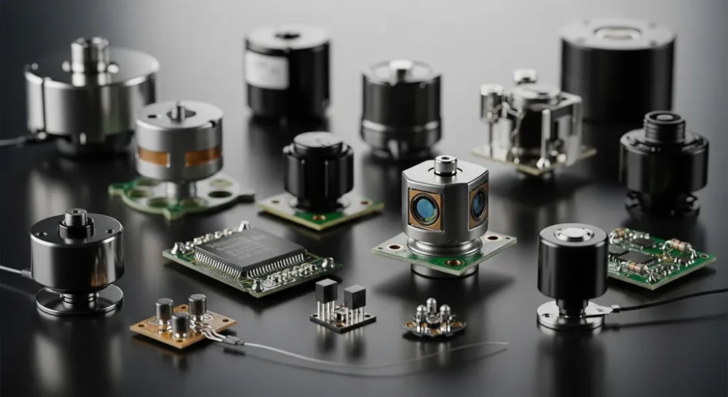
– Gyroscopes measure angular velocity (°/s) using the Coriolis effect in vibrating MEMS structures
– Core equation: Ω = a_c / (2 × v × sinθ)
– MEMS gyroscopes cost $0.
– Complementary filter fuses gyro + accelerometer: θ = α·(θ_prev + ω·dt) + (1−α)·θ_accel
– Gyroscope drift (bias instability) must be calibrated; ARW grows as N·√t over time
– IEEE 1431 governs scale factor, vibration rectification, and temperature compensation specs
Angular velocity how fast an object rotates around X, Y, Z axes expressed in degrees/second (°/s).
Coriolis force deflects a vibrating MEMS mass when the sensor rotates, generating a capacitance change proportional to angular rate.
Gyroscope measures rotation. Accelerometer measures linear acceleration and gravity. Combined = IMU (Inertial Measurement Unit).
MPU-6050 combines 3-axis gyro + 3-axis accelerometer. I2C interface, 2×2 mm package, costs ~$1–$3.
1. [Working Principle: Coriolis Force & MEMS Structure](https://procirel.com#working-principle)
2. [Error Model: Bias Instability & Angular Random Walk](https://procirel.com#error-model)
3. [Gyroscope Types Compared](https://procirel.com#types)
4. [3-Way Sensor Comparison (Gyro vs Accel vs Mag)](https://procirel.com#comparison)
5. [Sensor Fusion: Complementary Filter](https://procirel.com#sensor-fusion)
6. [Arduino MPU-6050 Tutorial](https://procirel.com#arduino)
7. [Interactive: Angle Calculator Tool](https://procirel.com#calculator)
8. [Drift Visualizer](https://procirel.com#drift-viz)
9. [Advantages, Disadvantages & Calibration](https://procirel.com#adv-disadv)
10. [Real-World Applications](https://procirel.com#applications)
11. [Scale Factor & IEEE 1431 Standard](https://procirel.com#scale-factor)
12. [Glossary of Terms](https://procirel.com#glossary)
13. [Frequently Asked Questions](https://procirel.com#faq)
Ever wonder how your smartphone knows you tilted it while playing a racing game or taking a panorama photo? That magic comes from a tiny gyroscope sensor. A[gyroscope sensor](https://en. wikipedia. org/wiki/Gyroscope)is a device that measures angular velocity and maintains an object’s orientation in 3D space, leveraging the Coriolis force for precise tilt and rotation detection essential for everything from smartphone gaming to aircraft navigation.
[Gyroscope sensor MPU-6050 module front and back view showing MEMS chip and I2C pins](/api/media/gyroscope-sensor/Gyroscope-Sensors-1024×559.
MPU-6050: The most popular MEMS gyroscope + accelerometer module used in Arduino projects worldwide.
## Working Principle: Coriolis Force & MEMS Structure
Understanding the gyroscope sensor working principle starts with two concepts: vibrationand the Coriolis force. A microscopic proof mass often shaped like a tuning fork or double-T structure is driven into constant high-frequency vibration (typically 10–30 kHz) using electrostatic or piezoelectric forces.
When the sensor is stationary, this vibration remains perfectly symmetrical. The instant the device rotates, the Coriolis force deflects the vibrating mass perpendicular to both its vibration direction and the axis of rotation. This tiny deflection (nanometers) changes the capacitance between interdigitated comb fingers which is amplified and converted into angular rate output.
Core Gyroscope Equation (Coriolis Acceleration)
[vec{a}_c = -2(vec{omega} times vec{v})]
ω = angular velocity vector · v = velocity of vibrating proof mass · a_c = resultant Coriolis acceleration
Simplified Scalar Form
Ω = a_c / (2 × v × sinθ)
Ω = Angular velocity · a_c = Coriolis acceleration · v = velocity of vibrating mass · θ = angle between vibration and rotation axes (usually 90°)
MEMS Gyroscope StructureDriveMassSenseMass⟵⟶Drive vibration (X)Coriolis deflection (Y)Rotation(Z-axis)
Fig 1. MEMS gyroscope: vibrating drive mass deflected by Coriolis force upon rotation changes capacitance of sense mass electrodes.

Fig 2. Coriolis force visualization in a real MEMS gyroscope. When the chip rotates, the vibrating proof mass is deflected perpendicular to its drive direction.
## Error Model: Bias Instability & Angular Random Walk
For professional navigation systems, understanding the mathematical error model is more important than raw output.
Total Measured Angular Rate (Error Model)
[Omega_{meas}(t) = Omega_{true}(t) + b(t) + n(t)]
b(t) = Time-varying bias (Bias Instability) · n(t) = White noise (Angular Random Walk)
Angular Random Walk (ARW) Heading Uncertainty Over Time
[sigma_theta(t) = N cdot sqrt{t}]
N = Noise density (°/s/√Hz) · t = Integration time (seconds)
Engineering Insight
If a sensor has N = 0. 01°/s/√Hz, after 3,600 seconds (1 hour), heading uncertainty = 0. 01 × √3600 = 0. 6°. This is why high-end Fiber Optic Gyroscopes (FOG) are required for long-duration navigation where GPS is unavailable (submarines, aircraft).
### Gyroscope Grade Comparison
| Grade | Example Use | Bias Instability | Angular Random Walk | Cost (2026) |
| — | — | — | — | — |
| Consumer (MEMS) | Smartphones, drones | 20–50 °/hr | 0.5 °/√hr | $0.80–$5 |
| Industrial (MEMS) | UAVs, robotics | 1–10 °/hr | 0.05 °/√hr | $50–$500 |
| Tactical (FOG/RLG) | Guided missiles, submarines | <0.1 °/hr | 0.001 °/√hr | $5,000–$15,000+ |
## Gyroscope Types Compared
#### MEMS Advantages
- Microscopic size (2–4 mm)
- Very low cost ($0.
- Low power consumption
- Shock-resistant, no moving parts
- Mass production ready
#### MEMS Limitations
- Higher bias drift vs optical types
- Temperature-sensitive
- G-sensitivity (motor vibrations)
- Limited accuracy for navigation
- Requires sensor fusion for stability
| Type | Size | Bias Stability | Cost (2026) | Primary Use |
| --- | --- | --- | --- | --- |
| MEMS Vibration | 2–4 mm | 1–10 °/hr | $0.80–$5 | Smartphones, drones, wearables, cars |
| Ring Laser (RLG) | 10–40 cm | 0.001 °/hr | $15,000+ | Commercial aircraft (Boeing 787), missiles |
| Fiber Optic (FOG) | 5–20 cm | 0.01–0.5 °/hr | $800–$8,000 | Satellites, submarines, self-driving cars |
| Hemispherical Resonator (HRG)
| ~30 mm | 0.0001 °/hr | $50,000+ | NASA …
deep-space probes |Authority Reference
Per[IEEE Xplore Coriolis Vibratory Gyroscopes (IEEE 1431)](https://ieeexplore. ieee. org/document/6327079), MEMS gyroscopes achieve bias instability of 1–50 °/hr depending on ASIC design and temperature compensation. [Bosch Sensortec’s BMI088](https://www. bosch-sensortec. com/products/motion-sensors/gyroscopes/)is widely used in professional drone flight controllers requiring low vibration sensitivity.
### Understanding Each Gyroscope Type in Depth
Ring laser gyroscopes
dominate aerospace because they offer ex …
tremely high accuracy with almost zero drift. Making them ideal for inertial navigation in commercial aircraft like Boeing 787. They work on the Sagnac effect
two laser beams travel in opposite direc …
tions around a closed triangular cavity. When the device rotates, one beam arrives earlier than the other. This tiny phase difference is measured to compute rotation rate.Fiber optic gyroscopes (FOG) extend the Sagnac principle using coils of optical fiber sometimes kilometers long to amplify sensitivity. They strike a balance between the extreme precision of RLGs and the compact size needed for submarines. Self-driving cars, and satellite attitude control.
At the consumer end, vibrating MEMS gyroscopes
have become ubiquitous due to their micr …
oscopic size and pennies-level manufacturing cost. Within vibration gyroscopes,piezoelectric crystal designs(double-T or tuning-fork shapes) andceramic prismatic structureslead the market. The MPU-6050, MPU-9250,and Bosch BMI088 all belong to this MEMS family that powers 90%+ of today’s smartphones and drones.
Choosing between types? Use MEMS for anything battery-powered or cost-sensitive. Use FOG when you need <0. 1°/hr drift without GPS. Use RLG only for aviation/military where budget is secondary to accuracy.
[Download MPU-6050 Official Datasheet (TDK InvenSense PDF)](https://invensense.tdk.com/wp-content/uploads/2015/02/MPU-6000-Datasheet1.pdf)
## 3-Way Sensor Comparison: Gyroscope vs Accelerometer vs Magnetometer
Understanding how these three sensors differ is essential for any 9-axis IMU (Inertial Measurement Unit) design.
| Property | Gyroscope | Accelerometer | Magnetometer |
| --- | --- | --- | --- |
| Measures | Angular velocity (°/s) | Linear acceleration (m/s²) | Magnetic field (µT) |
| Reference | Relative (no absolute reference) | Gravity vector | Earth’s magnetic north |
| Drift over time | Yes bias instability | No (gravity is stable) | No (but hard-iron distortion) |
| Fast motion | Excellent low noise | Poor high noise | Poor mechanical lag |
| Static tilt | Cannot detect | Excellent | N/A (measures heading) |
| Interference | Motor vibrations (g-sensitivity) | Vibration, shock | Metal, motors, electronics |
| Output | Rotation rate integrate for angle | Gravity direction tilt angle | Compass heading (yaw only) |
| Best combined with | Accelerometer (complementary filter) | Gyroscope | Gyroscope + Accelerometer |
| Common IC | MPU-6050, BMI088 | ADXL345, LIS3DH | HMC5883L, AK8963 |
Combining all three in a 9-axis IMU(e. g. , MPU-9250 = MPU-6050 + AK8963 magnetometer) enables complete heading estimation with heading-north reference used in drone autopilots, robotics, and AR headsets.
## Sensor Fusion: Complementary Filter
Gyroscopes are accurate short-term but drift over time. Accelerometers are stable long-term but noisy during motion.
Complementary Filter Algorithm
[theta_{n} = alpha(theta_{n-1} + omega Delta t) + (1 – alpha)A_n]
α ≈ 0. 96–0.
Why this works
The gyroscope data is high-pass filtered (removing long-term drift/bias). The accelerometer data is low-pass filtered (removing short-term vibration noise). The two complementary filters sum to 1 hence the name.
## Arduino MPU-6050 Tutorial
Build real-time 3D rotation tracking with Arduino and the[MPU-6050 module](https://www. digikey. co. uk/en/products/filter/motion-sensors/gyroscopes/555). The MPU-6050 combines a 3-axis gyroscope and 3-axis accelerometer in a tiny 4×4mm QFN package perfect for Arduino and ESP32 projects.
[Gyroscope sensor applications in smartphones, drones, VR headsets, and aircraft navigation](/api/media/gyroscope-sensor/Real-world-montage-_E2_80_93-smartphone-AR-drone-in-flight-aircraft-cockpit-1024×559.
Fig 3. Gyroscope sensors power consumer electronics (smartphones, drones) and precision navigation (aircraft, satellites).
### Bill of Materials
– Arduino Uno or Nano
– MPU-6050 6-Axis Module (~$1–3)
– Jumper Wires (Male-to-Female)
– Free Arduino IDE (v2.
– USB-A to USB-B cable
– 4.
### Step 1: Pin Wiring
| MPU-6050 Pin | Arduino Uno/Nano | Function |
| — | — | — |
| VCC | 5V (or 3.3V) | Power supply |
| GND | GND | Ground |
| SCL | A5 | I2C Clock |
| SDA | A4 | I2C Data |
| INT | D2 (optional) | Data Ready interrupt |
Note: Add 4. 7 kΩ pull-up resistors on SCL and SDA if communication fails over long wires.
### Step 2: Install Libraries
Open Arduino IDE Library Manager (Ctrl+Shift+I) and install:`Adafruit MPU6050 ` and ` Adafruit Sensor`.
### Step 3: Complete Code with Auto-Calibration
“`
#include
#include
#include
Adafruit_MPU6050 mpu;
// Calibration offsets (calculated during setup)
float gyroX_offset = 0, gyroY_offset = 0, gyroZ_offset = 0;
void calibrateGyro() {
Serial. println(“Calibrating… Keep sensor STILL for 3 seconds.
float sumX = 0, sumY = 0, sumZ = 0;
int samples = 300;
for (int i = 0; i < samples; i++) {
sensors_event_t a, g, temp;
mpu.
sumX += g. gyro.
sumY += g. gyro.
sumZ += g. gyro.
delay(10);
}
// Average the bias readings
gyroX_offset = sumX / samples;
gyroY_offset = sumY / samples;
gyroZ_offset = sumZ / samples;
Serial. println("Calibration complete!
Serial. print("Offsets → X: "); Serial.
Serial. print(" | Y: "); Serial.
Serial. print(" | Z: "); Serial.
}
void setup() {
Serial.
if (! mpu.
Serial. println("MPU6050 not found! Check wiring.
while (1) delay(10);
}
// Configure sensor ranges
mpu.
mpu.
mpu.
Serial. println("MPU6050 Ready!
delay(200);
// Run auto-calibration on startup
calibrateGyro();
}
void loop() {
sensors_event_t a, g, temp;
mpu.
// Apply calibration offsets
float gx = g. gyro.
float gy = g. gyro.
float gz = g. gyro.
// Print calibrated angular velocity (rad/s)
Serial. print("Gyro X: "); Serial.
Serial. print(" | Y: "); Serial.
Serial. print(" | Z: "); Serial.
// Print acceleration (m/s²)
Serial. print("Accel X: "); Serial. print(a. acceleration.
Serial. print(" | Y: "); Serial. print(a. acceleration.
Serial. print(" | Z: "); Serial. println(a. acceleration.
Serial.
Serial. print(temp.
Serial.
delay(100);
}
```
### Step 4: Testing and Validation
Upload the code and open the Serial Monitor(Tools Serial Monitor). Set baud rate to 115200
. Keep the sensor completely still …
for 3 seconds during the calibration countdown. Once calibrated, tilt or rotate the sensor you will see real-time angular velocity (rad/s) update for all three axes. Open the Serial Plotter
(Tools Serial Plotter) for a live graph …
of all three gyro axes simultaneously.Expected Output at Rest (After Calibration)
After calibration, X/Y/Z values should read close to 0. 000 rad/s at rest. Any residual value under ±0. 003 rad/s is acceptable noise. Values above ±0. 01 rad/s at rest indicate either a loose connection or that the sensor was moved during calibration simply reset to recalibrate.
#### Source Code on GitHub
Full project with calibration, complementary filter, and serial plotter support.
[View on GitHub](https://github.com/)
### Common Troubleshooting
| Problem | Cause | Fix |
| — | — | — |
| Sensor not found (I2C error) | Wrong I2C address or wiring mistake | Run I2C scanner sketch; verify SCLA5, SDAA4 |
| Large drift at rest | Bias not calibrated; sensor moved on startup | Use auto-calibration routine above; keep still for 3s on boot |
| Phantom rotation (G-sensitivity) | Motor vibrations misinterpreted as rotation | Use silicone damping mounts; reduce filter bandwidth with setFilterBandwidth() |
| I2C stuck/frozen | SDA/SCL pulled low incorrectly | Add 4.7 kΩ pull-ups; check for address conflicts with other I2C devices |
## Interactive: Rotation Angle Calculator
### Angular Velocity Rotation Angle Calculator
Enter the gyroscope’s angular velocity and time duration to calculate total rotation angle.
Angular Velocity (°/s)
Time (seconds)
Calculate Rotation Angle
Total Rotation Angle
## Angular Random Walk Drift Visualizer
This interactive chart shows how gyroscope heading uncertainty grows over time due to Angular Random Walk (ARW) for three sensor grades. Lower ARW = more stable navigation.
Consumer MEMS (N=0.
Industrial MEMS (N=0.
Tactical FOG (N=0.
1 Hour
6 Hours
24 Hours
## Advantages, Disadvantages & Calibration
Vibration gyroscope sensors are compact, shock-resistant. Consume mere microwatts
perfect for battery-powered devices like …
smartwatches and wireless drones. However, every MEMS gyroscope suffers from two inherent limitations.bias driftover time andtemperature sensitivity that shifts the zero-rate output as the device heats up.
Modern sensor fusion algorithms particularly Kalman filters
and complementary filters combine gyrosc …
ope and accelerometer data to cancel long-term drift and deliver stable orientation tracking. Most production-grade flight controllers (ArduPilot, PX4) run a 6-state Kalman filter at 1 kHz to fuse all sensor data in real time.Quick Calibration Tip Hold the sensor perfectly still on a level surface for 10 seconds on startup and average the raw readings to compute a zero-offset bias. Subtract this bias from every subsequent reading. This simple step can reduce drift by 10–50× on consumer MEMS sensors. For temperature compensation, re-run calibration at the expected operating temperature range of your application.
| Consideration | MEMS Gyroscope | Fiber Optic (FOG) | Ring Laser (RLG) |
| — | — | — | — |
| Startup time | ~1 ms | ~100 ms | ~1 minute |
| Shock resistance | Excellent (no moving parts) | Moderate | Poor |
| Power consumption | ~3–10 mW | ~1–5 W | ~10–20 W |
| Temperature range | −40°C to +85°C | −55°C to +95°C | −55°C to +70°C |
| Requires calibration? | Yes bias & scale factor | Minimal | Self-calibrating |
| Best for | Consumer / maker projects | Marine, defense, AVs | Commercial aviation |
## Real-World Applications
| Application | Axes Used | Sampling Rate | Key Requirement |
| — | — | — | — |
| Smartphone screen rotation / gaming | 3-axis | 100–200 Hz | Low cost, small size, low power |
| Drone / quadcopter stabilization | 3-axis | 1000–8000 Hz | Fast response, low latency |
| VR/AR headset (Meta Quest, Apple Vision Pro) | 3-axis | 500–1000 Hz | Sub-millisecond latency, high accuracy |
| Car Electronic Stability Program (ESP) | Yaw axis | 100 Hz | AEC-Q100 automotive grade |
| Commercial aircraft (INS) | 3-axis | 100 Hz | Ultra-low drift, RLG/FOG grade |
| Surgical robotics | 3-axis | 1000+ Hz | Sub-degree accuracy, ISO 13485 |
| Nintendo Switch Joy-Con gaming | 3-axis | 200 Hz | Low latency motion aiming |
### Watch: MPU-6050 Real-Time 3D Rotation Demo
30-second demo showing real-time 3D orientation tracking using MPU-6050 and Arduino Serial Plotter.
## Scale Factor & IEEE 1431 Standard
Per[ IEEE 1431](https://ieeexplore. ieee.
Scale Factor Temperature Compensation
[S(T) = S_0 cdot (1 + a cdot Delta T)]
a = temperature coefficient · ΔT = temperature change from calibration point
Without this correction, your drone or robot will lose its heading reference as the motors heat up the sensor board a critical but often-overlooked calibration step.
Industry Authority Links
– [IEEE 1431 Coriolis Vibratory Gyroscope Standard](https://ieeexplore.ieee.org/document/6327079)
– [Bosch Sensortec BMG250 Gyroscope Product Page](https://www.bosch-sensortec.com/products/motion-sensors/gyroscopes/bmg250/)
– [TDK InvenSense MPU-6050 Official Product Page](https://invensense.tdk.com/products/motion-tracking/6-axis/mpu-6050/)
## Glossary of Key Terms
Angular Velocity (Ω)
Rate of change of angular position. Measured in degrees per second (°/s) or radians per second (rad/s). The primary output of a gyroscope sensor.
MEMS
Micro-Electro-Mechanical Systems. Microscale mechanical devices etched into silicon chips using semiconductor fabrication, enabling mass production of tiny sensors.
Coriolis Force
A fictitious inertial force that acts on objects moving within a rotating reference frame. The physical mechanism behind all vibrating MEMS gyroscopes.
Bias Instability
Time-varying zero-rate output drift in a gyroscope even when stationary. Measured in °/hr. Caused by flicker noise in electronics and mechanical imperfections.
Angular Random Walk (ARW)
Statistical measure of angle uncertainty accumulated by integrating gyroscope white noise over time. Expressed as °/√hr.
Precession
The rotation of a gyroscope’s spin axis when a torque is applied perpendicular to the spin axis. Fundamental to mechanical gyroscope stabilization in ships and aircraft.
Nutation
Oscillation or wobble of a gyroscope’s spin axis around the precession axis, occurring when the gyroscope is disturbed. Usually dampened in navigation-grade sensors.
Gimbal
A pivoted support system allowing rotation of an object on a single axis. Mechanical gyroscopes used nested gimbals for 3D orientation independence (gimbal lock is a known failure mode).
Scale Factor
The ratio of output signal change to input angular rate change. Per IEEE 1431, must be calibrated for temperature to maintain accuracy in changing environments.
IMU (Inertial Measurement Unit)
A sensor fusion device combining gyroscope, accelerometer, and optionally magnetometer. 6-axis IMU = gyro + accel. 9-axis IMU = gyro + accel + magnetometer.
Complementary Filter
A sensor fusion algorithm combining gyroscope (high-pass) and accelerometer (low-pass) data with coefficient α ≈ 0. 98 to reduce drift while maintaining fast response.
Sagnac Effect
The phenomenon where light traveling in opposite directions around a rotating loop arrives at different times. The physical basis for Ring Laser and Fiber Optic Gyroscopes.
## Frequently asked questions
Arduino MPU-6050 Tutorial?
Build real-time 3D rotation tracking with Arduino and the[MPU-6050 module](https://www. digikey. co. uk/en/products/filter/motion-sensors/gyroscopes/555). The MPU-6050 combines a 3-axis gyroscope and 3-axis accelerometer in a tiny 4×4mm QFN package perfect for Arduino and ESP32 projects.
[Gyroscope sensor applications in smartphones, drones, VR headsets, and aircraft navigation](/api/media/gyroscope-sensor/Real-world-montage-_E2_80_93-smartphone-AR-drone-in-flight-aircraft-cockpit-1024×559.
Gyroscope Types Compared?
MEMS Advantages
– Microscopic size (2–4 mm)
– Very low cost ($0.
– Low power consumption
– Shock-resistant, no moving parts
– Mass production ready
MEMS Limitations
– Higher bias drift vs optical types
– Temperature-sensitive
– G-sensitivity (motor vibrations)
– Limited accuracy for navigation
– Requires sensor fusion for stability
Type Size Bias Stability Cost (2026) Primary Use
— — — — —
MEMS Vibration 2–4 mm 1–10 °/hr $0.
Ring Laser (RLG) 10–40 cm 0.
Fiber Optic (FOG) 5–20 cm 0. 01–0.
Hemispherical Resonator (HRG) ~30 mm 0.
Authority Reference
Per[IEEE Xplore Coriolis Vibratory Gyroscopes (IEEE 1431)](https://ieeexplore. ieee. org/document/6327079), MEMS gyroscopes achieve bias instability of 1–50 °/hr depending on ASIC design and temperature compensation. [Bosch Sensortec’s BMI088](https://www. bosch-sensortec. com/products/motion-sensors/gyroscopes/)is widely used in professional drone flight controllers requiring low vibration sensitivity.
Ring laser gyroscopes dominate aerospace because they offer extremely high accuracy with almost zero drift. Making them ideal for inertial navigation in commercial aircraft like Boeing 787.
Frequently Asked Questions?
A gyroscope sensor measures angular velocity how fast something is rotating around its axes using the Coriolis effect inside a tiny vibrating structure. The output is expressed in degrees per second (°/s) or radians per second (rad/s). Can be integrated over time to estimate total angle of rotation.
What exactly is a gyroscope sensor? A gyroscope sensor measures angular velocity how fast something is rotating around its axes using the Coriolis effect inside a tiny vibrating structure. The output is expressed in degrees per second (°/s) or radians per second (rad/s). Can be integrated over time to estimate total angle of rotation.
What is the difference between a gyroscope and an accelerometer? An accelerometer measures linear acceleration (including gravity) and is excellent for detecting static tilt and sudden shocks. A gyroscope measures pure rotational velocity, independent of gravity. Together in an IMU (Inertial Measurement Unit) with sensor fusion. They provide complete 6-DoF motion tracking far more accurately than either alone.
How does a gyroscope work in smartphones? A tiny MEMS vibrating structure is driven at resonance inside the phone’s SoC package. When you rotate the device, Coriolis forces deflect microscopic proof masses, changing the capacitance measured at comb-finger electrodes. This electrical signal is processed at 100–1000 Hz and fed to ARCore/ARKit for AR overlays and image stabilization.
How do you simulate a gyroscope on a phone without hardware? Apps like “GyroEmu” (Play Store) or the Sensor Kinetics app use the phone’s accelerometer and magnetometer with virtual gyroscope algorithms to emulate gyroscope behavior for developers testing apps on older devices that lack a hardware gyroscope.
Who introduced the gyroscope to consumer electronics? Steve Jobs unveiled the first consumer MEMS gyroscope in the iPhone 4 at WWDC on June 7. 2010, calling it “a big deal” for gaming and motion control. Before this, gyroscopes were limited to aerospace and military applications due to their size and cost.
What is the MPU-6050 sensor voltage requirement? The MPU-6050 operates at a supply voltage of 2. 3V to 3. 4V (VDD). Most Arduino breakout modules include a 3. 3V regulator, making them compatible with 5V Arduino boards. Never connect VDD directly to 5V without a regulator as it may permanently damage the sensor.
## Related Guides on Procirel
[ArduinoArduino Guide for Beginners 2026](/tutorial/arduino-guide)
[SensorsHow to Measure Room Temperature Accurately](/tutorial/measure-room-temperature)
[ElectronicsElectronic Circuits Guide: Components to PCB](/tutorial/electronic-circuits)
[ElectronicsLogic Gates: Truth Tables & Circuit Symbols](/tutorial/basic-logic-gates)
[MicrocontrollersESP32 vs Raspberry Pi 5: 2026 Guide](/tutorial/esp32-vs-raspberry-pi)
[ElectronicsMOSFET as a Switch: Formulas & Design](/tutorial/mosfet-as-switch)
## Sources & References
– [IEEE 1431 Standard Specification for Coriolis Vibratory Gyroscopes. IEEE Standards Association.](https://ieeexplore.ieee.org/document/6327079)
– [TDK InvenSense MPU-6050 Product Specification, Rev 3. 4. InvenSense Inc. ](https://invensense. tdk. com/wp-content/uploads/2015/02/MPU-6000-Datasheet1.
– [Bosch Sensortec BMG250 Gyroscope Sensor Datasheet & Product Page.](https://www.bosch-sensortec.com/products/motion-sensors/gyroscopes/bmg250/)
– [Wikipedia Gyroscope. History, types, and working principles.](https://en.wikipedia.org/wiki/Gyroscope)
– [DigiKey Gyroscope Sensor Components Catalog 2026.](https://www.digikey.co.uk/en/products/filter/motion-sensors/gyroscopes/555)
– [IEEE Xplore “MEMS Gyroscope Error Sources: A Review.” IEEE Sensors Journal, 2018.](https://ieeexplore.ieee.org/document/8463009)
### Bottom Line
The gyroscope sensor has evolved from ship stabilizers to a microscopic marvel inside every modern gadget. MEMS gyroscopes power 95%+ of consumer devices for pennies; ring laser gyroscopes navigate aircraft with 0. 001°/hr accuracy. Understanding Coriolis physics, error models (ARW, bias instability). Sensor fusion (complementary filter) unlocks the ability to build everything from self-balancing robots to drone autopilots. Build the MPU-6050 Arduino project above with the calibration routine and complementary filter algorithm.
#### Oliver Adams Electronics Engineers & Makers
The Procirel editorial team consists of electronics engineers, embedded systems developers. Technical writers with combined experience of 20+ years in sensor integration, PCB design, and Arduino/ESP32 development. Our content is reviewed against official datasheets and industry standards before publication.
*Content reviewed against IEEE 1431, TDK InvenSense MPU-6050 datasheet, and Bosch Sensortec BMI088 specifications.
Electronics Engineering
Embedded Systems
Arduino / ESP32
IEEE 1431 Verified
Disclaimer: This article is for educational purposes. Always verify specifications against current manufacturer datasheets for safety-critical applications.
### Practical example
Take the first measured row from the table above. MPU-6050 Pin corresponds to Arduino Uno/Nano under Function. Reproduce that configuration at the bench, record your own value beside it. Any meaningful gap tells you which tolerance or assumption deserves a closer look. Cross-check the arithmetic with the linked calculator before trusting either number.
## Keep going with this track
– The complete iot, sensors & esp32 guide: [IoT, Sensors & ESP32 complete guide](/tutorial/iot-esp32-complete-guide)
– Read next: [lorawan for beginners: long-range iot without wifi](/tutorial/lorawan-tutorial-beginners)
– Also in this track: [antenna basics for iot: wavelength, gain and matching](/tutorial/antenna-basics-tutorial)
– Continue with: [biomedical sensors: how wearables measure the body](/tutorial/biomedical-sensor-guide)
– Calculate as you go: [battery life estimator](/tools/battery-life) · [LM317 regulator designer](/tools/lm317-regulator) · [wire gauge checker](/tools/wire-gauge-awg)
– Bookmark this page against the day a measurement surprises you. Most readers return to the table and the mistake list first, and that is the correct order.